
- October 12, 2015
- Posted by: Surender Kumar
- Category: Cisco Routers
Multiple Site to Site VPN Tunnels on One Cisco Router
Table of Contents
In previous tutorials, we have looked into how to configure Site to Site VPN Tunnel between two routers. The traffic between both the routers is protected and encrypted by IPsec. In this section, we will discuss about configuring two VPN tunnels on the same router interface. This configuration is required if you have two branch offices at different locations and you want to connect each branch office to head office.
I will use the following network diagram for demonstration:
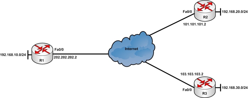
Consider that your company’s head office is located in Delhi (India) and Router R1 is your head office router connected to ISP via high speed link. The R2 and R3 routers are located in Sydney and Singapore respectively. You want to establish an IPsec VPN tunnel so that the private LAN connected behind R1 (192.168.10.0/24) can access the private LAN behind R2 (192.168.20.0/24) and R3 (192.168.30.0/24) and vice versa.
I will assume that basic network configuration is already done. All the routers are assigned a public IP address on outside interface and every router can ping each other since they are connected to internet.
Configuration of VPN Between R1 and R2
Let’s connect to R1 and start the configuration. First of all, I will create the ISKMP Phase 1 policy for remote router R1.
R1#conf t
Enter configuration commands, one per line.  End with CNTL/Z.
R1(config)#crypto isakmp policy 1
R1(config-isakmp)#encryption 3des
R1(config-isakmp)#hash md5
R1(config-isakmp)#group 2
R1(config-isakmp)#lifetime 86400
R1(config-isakmp)#authentication pre-share
R1(config-isakmp)#exit
R1(config)#crypto isakmp key Abc@123 address 101.101.101.2
R1(config)#
For details about above configuration commands, you can see the Site to Site IPsec VPN Tunnel section.
Now, I will create an extended access-list to identify the interesting traffic (traffic destined towards internal LAN behind R2 router).
R1(config)#ip access-list extended VPN-Traffic-To-R2
R1(config-ext-nacl)#permit ip 192.168.10.0 0.0.0.255 192.168.20.0 0.0.0.255
R1(config-ext-nacl)#end
R1#
The above access-list will allow only the traffic sourced from 192.168.10.0/24 subnet and destined towards 192.168.20.0/24 subnet to be sent over tunnel and this will also prevent the traffic destined towards internet not be encrypted.
Next step is to configure ISAKMP Phase-2.
R1(config)#
R1(config)#crypto ipsec transform-set set1 esp-3des esp-md5-hmac
R1(cfg-crypto-trans)#exit
R1(config)#crypto map CMAP 10 ipsec-isakmp
% NOTE: This new crypto map will remain disabled until a peer
        and a valid access list have been configured.
R1(config-crypto-map)#description ### Tunnel to R2 Router ###
R1(config-crypto-map)#set peer 101.101.101.2
R1(config-crypto-map)#set transform-set set1
R1(config-crypto-map)#match address VPN-Traffic-To-R2
R1(config-crypto-map)#end
R1#
Remember that set1 is the name of transform set which will be used for ISAKMP policy 1, CMAP is the name of crypto-map and 10 is the sequence number.
Sequence number plays an important role when you are going to configure multiple ISAKMP policies on a router which need to be applied on one interface since you can only apply one crypto-map to one router interface at one time. When we will configure second ISAKMP policy for router R2 then we will have to use same crypto-map (CMAP in this example) with different sequence number. Using different sequence numbers help us to apply one crypto-map to single router interface. In this way you can create any number of ISAKMP policies and then use them by assigning different sequence numbers in the same crypto-map.
Now, you can apply the crypto-map to router’s outside interface (connected to ISP) which is interface fastEthernet0/0 in our case. You can apply only one crypto-map per interface.
R1(config)#int fa0/0
R1(config-if)#crypto map CMAP
R1(config-if)#
*Oct 12 12:20:15.283: %CRYPTO-6-ISAKMP_ON_OFF: ISAKMP is ON
R1(config-if)#
Network Address Translation (NAT) is needed to be configured on R1 router to provide Internet access to PCs on internal LAN. This can be done by using another extended ACL on the router and this ACL will prevent the interesting traffic not to be translated, means the traffic sourced from 192.168.10.0/24 subnet and destined towards 192.168.20.0/24 subnet will not undergo NAT operation. The traffic destined towards internet will be translated.
R1(config)#ip access-list extended NO-NAT
R1(config-ext-nacl)#deny ip 192.168.10.0 0.0.0.255 192.168.20.0 0.0.0.255
R1(config-ext-nacl)#permit ip 192.168.10.0 0.0.0.255 any
R1(config-ext-nacl)#exit
R1(config)#ip nat inside source list NO-NAT interface fastEthernet 0/0 overload
R1(config)#int fa0/1
R1(config-if)#ip nat inside
R1(config-if)#int fa0/0
R1(config-if)#ip nat outside
R1(config-if)#end
For detailed NAT configuration, you can take a look at this section.
The VPN Tunnel configuration is done. The same configuration need to be done on R2 router located in remote branch office. The only difference in configuration will be that the public IP address of R1 router. Also the source and destination in ACLs need to be flipped. The complete configuration of R2 router is given below:
R2#config t
Enter configuration commands, one per line.  End with CNTL/Z.
R2(config)#crypto isakmp policy 1
R2(config-isakmp)#hash md5
R2(config-isakmp)#encryption 3des
R2(config-isakmp)#group 2
R2(config-isakmp)#lifetime 86400
R2(config-isakmp)#authentication pre-share
R2(config-isakmp)#crypto isakmp key Abc@123 address 202.202.202.2
R2(config)#ip access-list extended VPN-Traffic-To-R1
R2(config-ext-nacl)#permit ip 192.168.20.0 0.0.0.255 192.168.10.0 0.0.0.255
R2(config-ext-nacl)#
R2(config-ext-nacl)#crypto ipsec transform-set set1 esp-3des esp-md5-hmac
R2(cfg-crypto-trans)#crypto map CMAP 10 ipsec-isakmp
% NOTE: This new crypto map will remain disabled until a peer
        and a valid access list have been configured.
R2(config-crypto-map)#description ### Tunnel to R1 Router ###
R2(config-crypto-map)#set peer 202.202.202.2
R2(config-crypto-map)#set transform-set set1
R2(config-crypto-map)#match address VPN-Traffic-To-R1
R2(config-crypto-map)#int fa0/0
R2(config-if)#crypto map CMAP
*Jul 17 14:01:57.707: %CRYPTO-6-ISAKMP_ON_OFF: ISAKMP is ON
R2(config-if)#ip access-list extended NO-NAT
R2(config-ext-nacl)#deny ip 192.168.20.0 0.0.0.255 192.168.10.0 0.0.0.255
R2(config-ext-nacl)#permit ip 192.168.20.0 0.0.0.255 any
R2(config-ext-nacl)#exit
R2(config)#ip nat inside source list NO-NAT interface fastEthernet 0/0 overload
R2(config)#int fa0/1
R2(config-if)#ip nat inside
R2(config-if)#int fa0/1
R2(config-if)#ip nat outside
R2(config-if)#end
The VPN tunnel is now configured between R1 and R2 and it can be brought up by running ping from internal LAN behind either R1 or R2. Next step is to create VPN between R1 and R3 using same outside interface on R1 router.
Configuration of VPN Between R1 and R3
The configuration step will be almost same as above. The only difference is that we will not create different crypto-map but instead we will create a new entry with different sequence number in same crypto-map (CMAP in our case).
R1(config)#crypto isakmp policy 2
R1(config-isakmp)#hash md5
R1(config-isakmp)#encryption 3des
R1(config-isakmp)#group 2
R1(config-isakmp)#lifetime 86400
R1(config-isakmp)#authentication pre-share
R1(config-isakmp)#exit
R1(config)#crypto isakmp key Xyz@123 address 103.103.103.2
R1(config)#
In above configuration commands, I’ve created another ISAKMP policy 2. This policy can use different encryption, hashing algorithm and different preshared key but these settings must match on the router at remote location (R3 in this case).
Now, create a different extended access-list to match the interesting traffic. This traffic will be the traffic sourced from internal LAN behind R1 (192.168.10.0/24) and destined towards internal LAN behind R3 (192.168.30.0/24). I will also create a different transform-set (set2) to be used with ISAKMP policy 2.
R1(config)#ip access-list extended VPN-Traffic-To-R3
R1(config-ext-nacl)#permit ip 192.168.10.0 0.0.0.255 192.168.30.0 0.0.0.255
R1(config-ext-nacl)#exit
R1(config)#crypto ipsec transform-set set2 esp-3des esp-md5-hmac
R1(cfg-crypto-trans)#exit
You can use the existing trasform set (set1) with policy 2 as well but I would recommend creating new one since I’ve seen many people facing VPN performance issues when using same transform set with multiple ISAKMP policies.
Now, comes the most important step which will differentiate the VPN configuration from above. We will modify the use the existing crypto-map instead of creating new. I will use existing crypto-map and insert a new entry using sequence number 20. If you create a new crypto-map at this stage and apply it to outside interface of R1, it will replace the existing crypto-map which will cause the VPN between R1 and R2 to stop working.
R1(config)#crypto map CMAP 20 ipsec-isakmp
% NOTE: This new crypto map will remain disabled until a peer
        and a valid access list have been configured.
R1(config-crypto-map)#description ### Tunnel to R3 Router ###
R1(config-crypto-map)#set peer 103.103.103.2
R1(config-crypto-map)#set transform-set set2
R1(config-crypto-map)#match address VPN-Traffic-To-R3
R1(config-crypto-map)#exit
R1(config)#
The crypto-map is already applied on outside interface of router R1, so we do not need to re-apply it.
Now, you have to modify the NAT access-list to also include the traffic destined for internal LAN behind router R3 (192.168.3.0/24). To do this let’s take a look at access-list.
R1(config)#do show ip access-list NO-NAT
Extended IP access list NO-NAT
    10 deny ip 192.168.10.0 0.0.0.255 192.168.20.0 0.0.0.255
    20 permit ip 192.168.10.0 0.0.0.255 any
You see that there are only two entries in extended access-list marked with sequence numbers 10 and 20. The line 10 denies the traffic going towards LAN behind R2 so that the traffic will not get translated and the line 20 permits other traffic to undergo NAT translation. We have to insert a new line exactly between both the lines. To do this, I will use line 15 and insert the entry as shown below:
R1(config)#ip access-list extended NO-NAT
R1(config-ext-nacl)#15 deny ip 192.168.10.0 0.0.0.255 192.168.30.0 0.0.0.255
R1(config-ext-nacl)#exit
If you add the entry after line 20, the access-list will not behave as expected. For more information about modifying extended access-lists, you can take a look at this section. Now, take a look at access-list once again.
R1(config)#do show ip access-list NO-NAT
Extended IP access list NO-NAT
    10 deny ip 192.168.10.0 0.0.0.255 192.168.20.0 0.0.0.255
    15 deny ip 192.168.10.0 0.0.0.255 192.168.30.0 0.0.0.255
    20 permit ip 192.168.10.0 0.0.0.255 any
Notice that the line got inserted to the right place.
The VPN configuration is now complete on R1 for both destinations R2 and R3. You need to do the following configuration on R3 router.
R3#config t
Enter configuration commands, one per line.  End with CNTL/Z.
R3(config)#crypto isakmp policy 1
R3(config-isakmp)#hash md5
R3(config-isakmp)#encryption 3des
R3(config-isakmp)#group 2
R3(config-isakmp)#lifetime 86400
R3(config-isakmp)#authentication pre-share
R3(config-isakmp)#crypto isakmp key Xyz@123 address 202.202.202.2
R3(config)#ip access-list extended VPN-Traffic-To-R1
R3(config-ext-nacl)#permit ip 192.168.30.0 0.0.0.255 192.168.10.0 0.0.0.255
R3(config-ext-nacl)#
R3(config-ext-nacl)#crypto ipsec transform-set set1 esp-3des esp-md5-hmac
R3(cfg-crypto-trans)#crypto map CMAP 10 ipsec-isakmp
% NOTE: This new crypto map will remain disabled until a peer
        and a valid access list have been configured.
R3(config-crypto-map)#set peer 202.202.202.2
R3(config-crypto-map)#set transform-set set1
R3(config-crypto-map)#match address VPN-Traffic-To-R1
R3(config-crypto-map)#int fa0/0
R3(config-if)#crypto map CMAP
*Jul 17 14:01:57.707: %CRYPTO-6-ISAKMP_ON_OFF: ISAKMP is ON
R3(config-if)#ip access-list extended NO-NAT
R3(config-ext-nacl)#deny ip 192.168.30.0 0.0.0.255 192.168.10.0 0.0.0.255
R3(config-ext-nacl)#permit ip 192.168.30.0 0.0.0.255 any
R3(config-ext-nacl)#exit
R3(config)#ip nat inside source list NO-NAT interface fastEthernet 0/0 overload
R3(config)#int fa0/1
R3(config-if)#ip nat inside
R3(config-if)#int fa0/0
R3(config-if)#ip nat outside
R3(config-if)#end
After completing this step, our Site to Multi-site VPN configuration is ready.
The configuration on branch office routers is pretty straightforward since there is only one ISAKMP policy but the configuration of head office router R1 is somewhat different. Lets take a look at the complete configuration what we did on R1 so far.
R1#show running-config | begin crypto
crypto isakmp policy 1
 encr 3des
 hash md5
 authentication pre-share
 group 2
!
crypto isakmp policy 2
 encr 3des
 hash md5
 authentication pre-share
 group 2
crypto isakmp key Abc@123 address 101.101.101.2
crypto isakmp key Xyz@123 address 103.103.103.2
!
!
crypto ipsec transform-set set1 esp-3des esp-md5-hmac
 mode tunnel
crypto ipsec transform-set set2 esp-3des esp-md5-hmac
 mode tunnel
!
!
crypto map CMAP 10 ipsec-isakmp
 description ### Tunnel to R2 Router ###
 set peer 101.101.101.2
 set transform-set set1
 match address VPN-Traffic-To-R2
crypto map CMAP 20 ipsec-isakmp
 description ### Tunnel to R3 Router ###
 set peer 103.103.103.2
 set transform-set set2
 match address VPN-Traffic-To-R3
!
!
!
interface FastEthernet0/0
 ip address 202.202.202.2 255.255.255.252
 ip nat outside
 ip virtual-reassembly in
 duplex auto
 speed auto
 crypto map CMAP
!
interface FastEthernet0/1
 ip address 192.168.10.1 255.255.255.0
 ip nat inside
 ip virtual-reassembly in
 duplex auto
 speed auto
!

[output cut]

!
ip nat inside source list NO-NAT interface FastEthernet0/0 overload
!
ip access-list extended NO-NAT
 deny   ip 192.168.10.0 0.0.0.255 192.168.20.0 0.0.0.255
 deny   ip 192.168.10.0 0.0.0.255 192.168.30.0 0.0.0.255
 permit ip 192.168.10.0 0.0.0.255 any
ip access-list extended VPN-Traffic-To-R1
 permit ip 192.168.10.0 0.0.0.255 192.168.20.0 0.0.0.255
ip access-list extended VPN-Traffic-To-R3
 permit ip 192.168.10.0 0.0.0.255 192.168.30.0 0.0.0.255
!
You can confirm the status of ISAKMP session with the following command:
R1#show crypto isakmp sa
dst             src             state          conn-id slot status
202.202.202.2   101.101.101.2   QM_IDLE             1    0 ACTIVE
202.202.202.2   103.103.103.2   QM_IDLE             2    0 ACTIVE
If you see the state as QM_IDLE, it means ISAKMP negotiation is successful and your VPN tunnel is up and running.
You can use the information given in this section if you want one site to be able to access internal network on one or more remote site(s). But both remote sites (R2 and R3 in our case) will only be able to access internal LAN behind R1 and will not be able to access internal LAN behind each other. To do this you need to create seperate ISAKMP policies on both R2 and R3 routers as shown above.
In the next article, I’ll show you how to configure Dynamic Multipoint VPN (DMVPN).
Cisco DMVPN is a technology that allows multiple branch locations to communicate directly with each other over the public WAN (internet) without requiring a permanent VPN tunnel between sites. The best part is you can add any new site to existing topology with least administrative efforts.
7 Comments
Comments are closed.
Good job…
GREAT !!! Thanks a lot, I finaly managed to get working these VPNs
Thank you for writing. Please like & subscribe us on Social Media:
YouTube: https://www.youtube.com/techtutsonline
Facebook: https://www.facebook.com/techtutsonline
Google+: https://plus.google.com/+Techtutsonline
Twitter: https://twitter.com/techtutsonline
Thanks.
But, if you want the two branches to be available to reach each others LAN, in what steps do you need to do that?
Do you setup on of them like we did on R1? Is it only the ISAKMP policy number you will need to change or is it the set number aswall? 🙁
Hi,
This type of configuration is discussed in following article:
https://www.techtutsonline.com/cisco-dynamic-multipoint-vpn-dmvpn-configuration
Please like & subscribe me on social media if you find the content helpful.
YouTube: https://www.youtube.com/techtutsonline
Facebook: https://www.facebook.com/techtutsonline
Google+: https://plus.google.com/+Techtutsonline
Twitter: https://twitter.com/techtutsonline
Hi Surender.. What happens when both remote sites have traffic to send to the hub? Can two tunnels co-exist? Meaning can both the tunnels be active at the same time and the hub reply to both sites simultaneously over the same hub physical interface?
Hello Karthikiran,
If you are referring R1 as Hub then YES two tunnels can co-exist and can share the same interface for exchanging data at the same time. The problem with this approach is that you have to modify the configuration of R1 each time you want to add/remove the remote site.
DMVPN is a better approach which is discussed in the following article:
https://www.techtutsonline.com/cisco-dynamic-multipoint-vpn-dmvpn-configuration/
DMVPN is actually a Hub and Spoke configuration.