- July 25, 2017
- Posted by: Surender Kumar
- Category: Cisco Routers
Cisco Dynamic Multipoint VPN (DMVPN) Configuration
Table of Contents
Dynamic Multipoint VPN (DMVPN) is a Cisco IOS Software solution for building scalable IPsec Virtual Private Networks (VPNs).
Cisco DMVPN allows branch locations to communicate directly with each other over the public WAN (internet) without requiring a permanent VPN tunnel between sites. It enables zero-touch deployment of IPsec VPNs and improves network performance by reducing latency and jitter, while optimizing head office bandwidth utilization.
Benefits
- Lowers capital and operational expenses — Reduces costs in integrating voice, video with VPN security
- Simplifies branch communications — Enables direct branch-to-branch connectivity for business applications like voice
- Reduces deployment complexity — Offers a zero-touch configuration, dramatically reducing the deployment complexity in VPNs
- Improves business resiliency — Prevents disruption of business-critical applications and services by incorporating routing with standards-based IPsec technology
Network Diagram
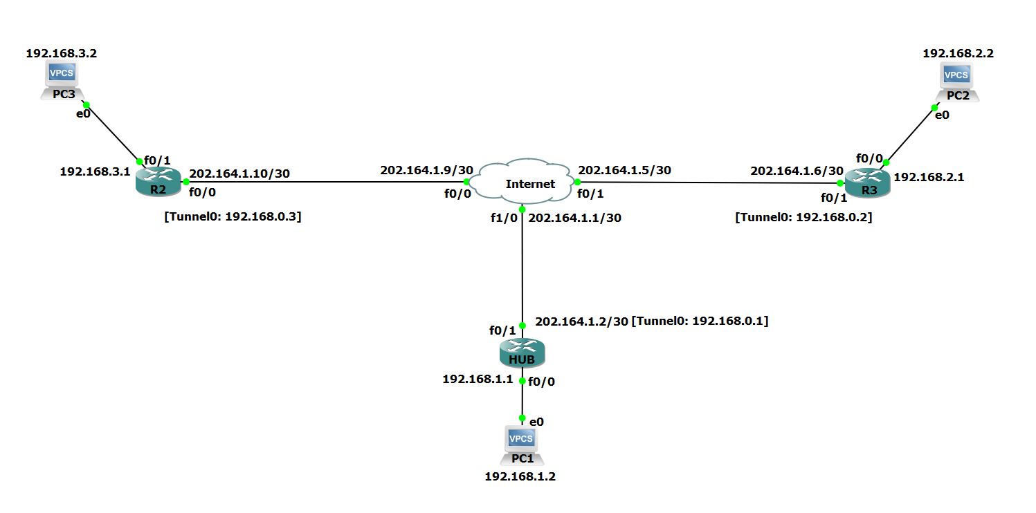
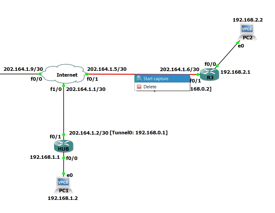
The following diagram represents our DMVPN network. Our goal is to enable the communication of 2 LANs that are behind routers R2 and R3 with company’s head office LAN which is behind HUB router. The head office router (HUB) is the central Hub router which will act as NHRP server containing information about all spoke routers (R1 & R2), their public IP addresses and LANs connected to them.
Configuration Steps
The whole DMVPN configuration contains following steps:
-
Configuring the Hub router
-
Configuring the Spoke routers
- Configuring the routing between GRE Tunnels
-
Protecting the tunnels with IPSec
Configuring the Hub Router
Following is the configuration of Outside and Inside interfaces of Hub router:
!
interface FastEthernet0/0
 description Inside
 ip address 192.168.1.1 255.255.255.0
 duplex auto
 speed auto
!
interface FastEthernet0/1
 description Outside
 ip address 202.164.1.2 255.255.255.252
 duplex auto
 speed auto
!
Following is the configuration of tunnel interface (Tunnel 0):
!
interface Tunnel0
 description DMVPN Tunnel
 ip address 192.168.0.1 255.255.255.0
 no ip redirects
 ip nhrp authentication cisco
 ip nhrp map multicast dynamic
 ip nhrp network-id 10
 tunnel source 202.164.1.2
 tunnel mode gre multipoint
!
Explanation of above configuration commands:
- ip address 192.168.0.1 255.255.255.0: This command configures the IP address on tunnel interface.
- no ip redirects: This disables icmp redirect messages. Redirects happen when a router recognizes a packet arriving on an interface and the best route is out that same interface. This command is highly recommended from a security point of view because ICMP redirect messages can be used by an attacker to generate network topology and perform network diagnosis.
- ip nhrp authentication cisco: This command allows you to specify a password for your DMVPN network so not just any GRE tunnel can join your DMVPN cloud. In our example cisco is the password.
- ip nhrp map multicast dynamic: This command allows NHRP to automatically map multicast traffic from other devices, without the need to statically configure each device.
- ip nhrp network-id 10: The NHRP network-id number ensures this DMVPN interface only participates within it’s own DMVPN network. Just in case you have more the one tunnel interface on the same router connected to two separate DMVPN clouds/networks. All routers participating in DMVPN cloud must have the same network-id configured in order for tunnels formation. We used 10 in our example.
- tunnel source 202.164.1.2: This command specifies the tunnel source. The static IP of Outside interface must be used for Hub router. in our example the IP is 202.164.1.2.
- tunnel mode gre multipoint: This command specifies that the tunnel interface is GRE multipoint, means this will be acting as single interface connected to multiple spokes.
Configuring the Spoke router (R2)
Following is the configuration of Inside and Outside interfaces of R2:
!
interface FastEthernet0/0
 description Outside
 ip address 202.164.1.10 255.255.255.252
 duplex auto
 speed auto
!
interface FastEthernet0/1
 description Inside
 ip address 192.168.3.1 255.255.255.0
 duplex auto
 speed auto
!
Following is the configuration of tunnel interface (Tunnel 0) on branch router R2:
!
interface Tunnel0
 description R2-DMVPN Tunnel
 ip address 192.168.0.3 255.255.255.0
 no ip redirects
 ip nhrp authentication cisco
 ip nhrp map multicast dynamic
 ip nhrp map 192.168.0.1 202.164.1.2
 ip nhrp map multicast 202.164.1.2
 ip nhrp network-id 10
 ip nhrp nhs 192.168.0.1
 tunnel source FastEthernet0/0
 tunnel mode gre multipoint
!
Explanation of above configuration commands:
- ip address 192.168.0.3 255.255.255.0: This command configures the IP address on tunnel interface.
- no ip redirects: This disables icmp redirect messages. Redirects happen when a router recognizes a packet arriving on an interface and the best route is out that same interface.
- ip nhrp authentication cisco: This command allows you to specify a password for your DMVPN network so not just any GRE tunnel can join your DMVPN cloud. In our example cisco is the password.
- ip nhrp map multicast dynamic: This command allows NHRP to automatically map multicast traffic from other devices, without the need to statically configure each device.
- ip nhrp map 192.168.0.1 202.164.1.2: This command maps the Next Hop Server address (192.168.0.1) to the Hub router’s public IP address (202.164.1.2).
- ip nhrp map multicast 202.164.1.2: This command specifies that the multicast traffic is sent only from spokes to Hub router and not from spoke to spoke.
- ip nhrp network-id 10: The NHRP network-id number ensures this DMVPN interface only participates within it’s own DMVPN network. Just in case you have more the one tunnel interface on the same router connected to two separate DMVPN clouds/networks. All routers participating in DMVPN cloud must have the same network-id configured in order for tunnels formation. We used 10 in our example.
- ip nhrp nhs 192.168.0.1: This command tells the spoke router who the Next Hop Server.
- tunnel source FastEthernet0/0: This command specifies the tunnel source as Outside interface of R2 (FastEthernet0/0 is our case). We could use the static IP of Outside interface (if available) but specifying the interface name helps in case Outside interface of spoke router has dynamic IP address which is provided by your ISP and it changes when router is restarted.
- tunnel mode gre multipoint: This command specifies that the tunnel interface is GRE multipoint, means this will be acting as single interface connected to multiple spokes.
Configuring the Spoke router (R3)
Configuration of all the spokes is almost same. Following is the configuration of R3 spoke router:
!
interface FastEthernet0/0
 description Inside
 ip address 192.168.2.1 255.255.255.0
 duplex auto
 speed auto
!
interface FastEthernet0/1
 description Outside
 ip address 202.164.1.6 255.255.255.252
 duplex auto
 speed auto
!
Following is the configuration of tunnel 0 interface:
!
interface Tunnel0
 description R3-DMVPN Tunnel
 ip address 192.168.0.2 255.255.255.0
 no ip redirects
 ip nhrp authentication cisco
 ip nhrp map multicast dynamic
 ip nhrp map 192.168.0.1 202.164.1.2
 ip nhrp map multicast 202.164.1.2
 ip nhrp network-id 10
 ip nhrp nhs 192.168.0.1
 tunnel source FastEthernet0/1
 tunnel mode gre multipoint
!
Configuring the Routing Between GRE Tunnels
Next step is to enable the routing in our DMVPN network. This is required so that the hub and spoke routers are aware which packets need to be sent via the VPN tunnel.
We will configure the static routes on all routers so that routers could route the traffic between LANs connected behind each router. You can also use routing protocols such as EIGRP or OSPF but we will only configure static route in our topology.
Static Route on Hub Router
!
ip route 0.0.0.0 0.0.0.0 202.164.1.1
ip route 192.168.2.0 255.255.255.0 192.168.0.2
ip route 192.168.3.0 255.255.255.0 192.168.0.3
!
In above configuration commands, first route is the default route which is needed so that LAN behind Hub router can connect to internet. Following 2 routes actually tells the router to reach the LAN behind branch office routers (R2 & R3) via Tunnel interface:
ip route 192.168.2.0 255.255.255.0 192.168.0.2
ip route 192.168.3.0 255.255.255.0 192.168.0.3
Static Route on Spoke Router R2
!
ip route 0.0.0.0 0.0.0.0 202.164.1.9
ip route 192.168.1.0 255.255.255.0 192.168.0.1
ip route 192.168.2.0 255.255.255.0 192.168.0.2
!
In above configuration commands, first route is the default route which is needed so that LAN behind spoke router R2 can connect to internet. Following 2 routes actually tells the router to reach the LAN behind routers (Hub & R3) via Tunnel interface:
ip route 192.168.1.0 255.255.255.0 192.168.0.1
ip route 192.168.2.0 255.255.255.0 192.168.0.2
Static Route on Spoke Router R3
!
ip route 0.0.0.0 0.0.0.0 202.164.1.5
ip route 192.168.1.0 255.255.255.0 192.168.0.1
ip route 192.168.3.0 255.255.255.0 192.168.0.3
!
In above configuration commands, first route is the default route which is needed so that LAN behind spoke router R3 can connect to internet. Following 2 routes actually tells the router to reach the LAN behind routers (Hub & R2) via Tunnel interface:
ip route 192.168.1.0 255.255.255.0 192.168.0.1
ip route 192.168.3.0 255.255.255.0 192.168.0.3
Checking The Progress
At this point, our DMVPN network is ready. All networks are connected to each other and dynamic VPN tunnels between spokes can be established.
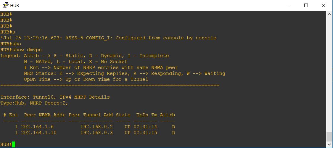
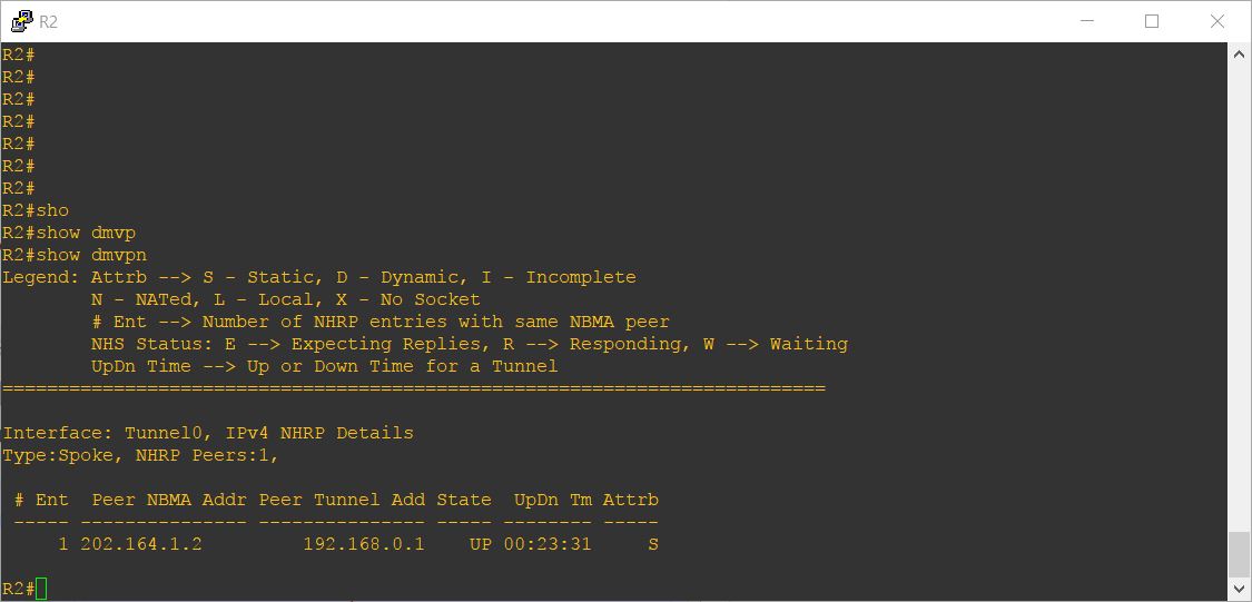
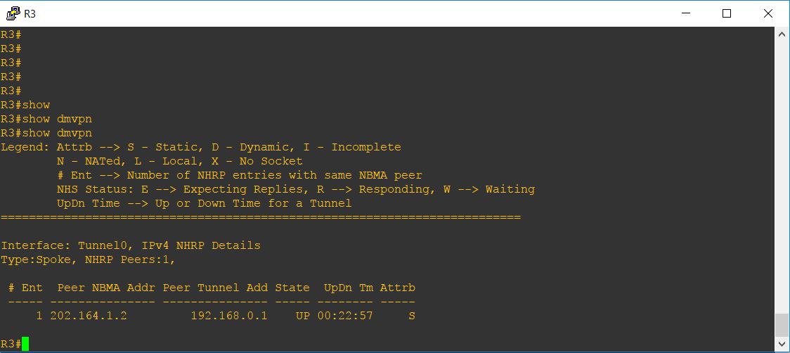
To view the status of DMVPN, you can use show dmvpn command on router. Below are the screenshots of show dmvpn command on all of our routers:
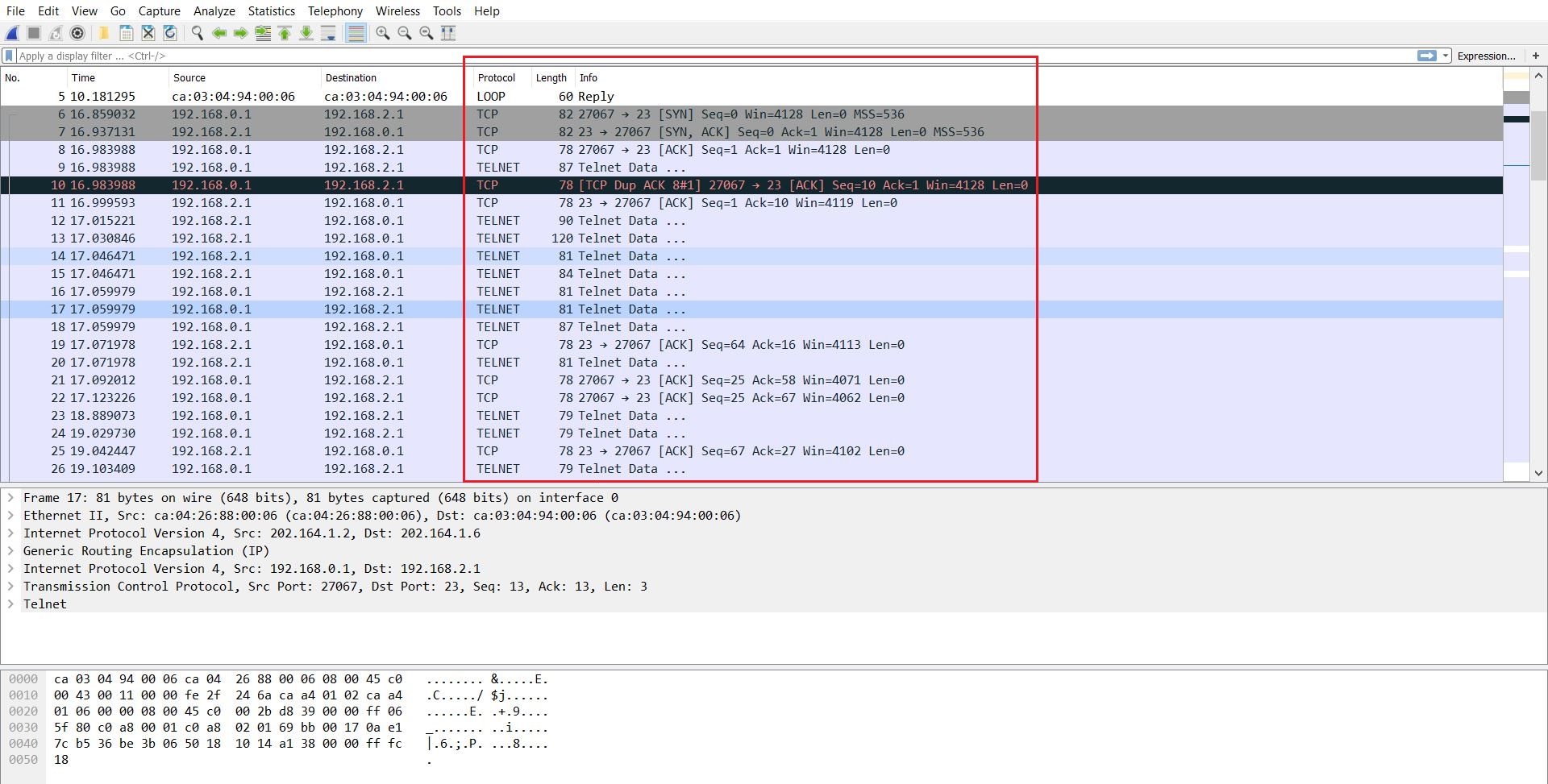
But since our data is flowing through internet, anybody can capture the packets and read the packets flowing through our tunnels since they are not encrypted by any means. To prove this, I am going to start a Wireshark capture of link between our Hub and Spoke router R3 and then I will try to telnet the Router R3 from our Hub router. You will see that the Wireshark capture will clearly display the type of traffic being transferred and therefore anybody can read the everything (including passwords).
Below is the snapshot of Wireshark capture:
You can clearly see the protocol type and data is shown as plain text in snapshot. This means our DMVPN network is very vulnerable till now. So, the final step is to encrypt the DMVPN mGRE tunnels with IPSec.
Encrypting the DMVPN mGRE tunnels with IPSec
Since our mGRE tunnels are running in vulnerability, we need to encrypt them using IPSec to ensure that if anybody manage to capture our traffic, he will still not be able to read it.
We will create the IPSec policy on our routers and apply the policy on tunnel interface (Tunnel 0). For detailed explanation of IPSec configuration you can visit Site-to-site IPSec VPN Tunnel article.
IPSec Configuration on Hub router
!
crypto isakmp policy 1
 encr 3des
 hash md5
 authentication pre-share
 group 2
crypto isakmp key techtuts address 0.0.0.0
!
!
crypto ipsec transform-set TS esp-3des esp-md5-hmac
 mode tunnel
!
!
crypto ipsec profile protected-gre-tunnel
 set security-association lifetime seconds 86400
 set transform-set TS
!
In above configuration command crypto isakmp key techtuts address 0.0.0.0, we used 0.0.0.0 which means it is valid for any IP address. You should use 0.0.0.0 if your spoke routers obtain dynamic public IP address for ISP.
Now apply the IPsec profile on Tunnel interface and final configuration of Tunnel 0 interface will look like below:
!
interface Tunnel0
 description DMVPN Tunnel
 ip address 192.168.0.1 255.255.255.0
 no ip redirects
 ip nhrp authentication cisco
 ip nhrp map multicast dynamic
 ip nhrp network-id 10
 tunnel source 202.164.1.2
 tunnel mode gre multipoint
 tunnel protection ipsec profile protected-gre-tunnel
!
IPSec Configuration on Spoke router R2
!
crypto isakmp policy 1
 encr 3des
 hash md5
 authentication pre-share
 group 2
crypto isakmp key techtuts address 0.0.0.0
!
!
crypto ipsec transform-set TS esp-3des esp-md5-hmac
 mode tunnel
!
!
crypto ipsec profile protect-gre-tunnel
 set security-association lifetime seconds 86400
 set transform-set TS
!
Remember that in crypto isakmp key techtuts address 0.0.0.0 command, we need to use 0.0.0.0 instead of assigning any IP so that routers R2 & R3 can dynamically build DMVPN tunnels between spoke to spoke.
Now apply the IPsec profile on Tunnel interface and final configuration of Tunnel 0 interface will look like below:
interface Tunnel0
 description R2-DMVPN Tunnel
 ip address 192.168.0.3 255.255.255.0
 no ip redirects
 ip nhrp authentication cisco
 ip nhrp map multicast dynamic
 ip nhrp map 192.168.0.1 202.164.1.2
 ip nhrp map multicast 202.164.1.2
 ip nhrp network-id 10
 ip nhrp nhs 192.168.0.1
 tunnel source FastEthernet0/0
 tunnel mode gre multipoint
 tunnel protection ipsec profile protect-gre-tunnel
!
IPSec Configuration on Spoke router R3
!
crypto isakmp policy 1
 encr 3des
 hash md5
 authentication pre-share
 group 2
crypto isakmp key techtuts address 0.0.0.0
!
!
crypto ipsec transform-set TS esp-3des esp-md5-hmac
 mode tunnel
!
!
crypto ipsec profile protect-gre-tunnel
 set security-association lifetime seconds 86400
 set transform-set TS
!
Now apply the IPsec profile on Tunnel interface and final configuration of Tunnel 0 interface will look like below:
!
interface Tunnel0
 description R3-DMVPN Tunnel
 ip address 192.168.0.2 255.255.255.0
 no ip redirects
 ip nhrp authentication cisco
 ip nhrp map multicast dynamic
 ip nhrp map 192.168.0.1 202.164.1.2
 ip nhrp map multicast 202.164.1.2
 ip nhrp network-id 10
 ip nhrp nhs 192.168.0.1
 tunnel source FastEthernet0/1
 tunnel mode gre multipoint
 tunnel protection ipsec profile protect-gre-tunnel
!
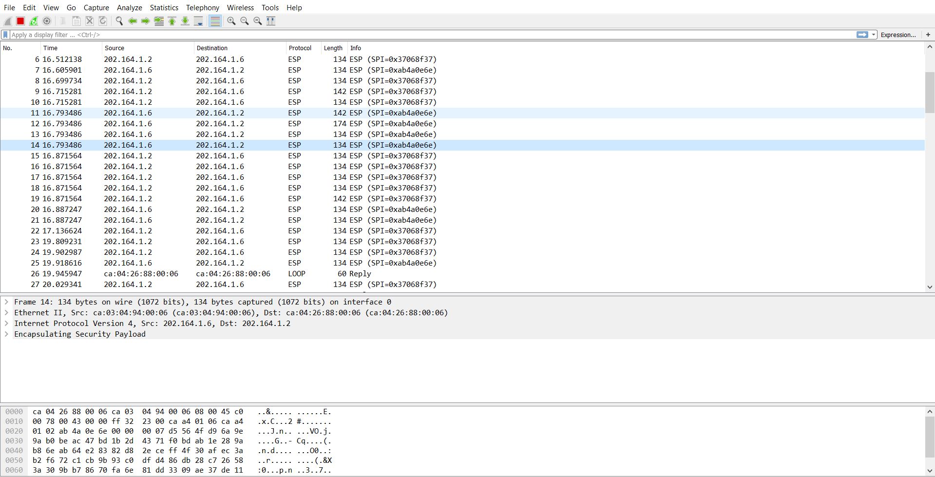
Now that our tunnels are protected with IPSec, if we run the Wireshark capture, you will notice that all the packets will be shown as ESP (Encapsulating Security Payload) and nobody could read the contents of packets.
Verifying the DMVPN Network
At this point our DMVPN network is fully configured and protected with IPSec. To verify the tunnels, you can use show crypto session command. The output of command is shown below:
HUB#show crypto session
Crypto session current status

Interface: Tunnel0
Session status: UP-ACTIVE
Peer: 202.164.1.6 port 500
 IKEv1 SA: local 202.164.1.2/500 remote 202.164.1.6/500 Active
 IPSEC FLOW: permit 47 host 202.164.1.2 host 202.164.1.6
 Active SAs: 2, origin: crypto map

Interface: Tunnel0
Session status: UP-ACTIVE
Peer: 202.164.1.10 port 500
 IKEv1 SA: local 202.164.1.2/500 remote 202.164.1.10/500 Active
 IPSEC FLOW: permit 47 host 202.164.1.2 host 202.164.1.10
 Active SAs: 2, origin: crypto map

HUB#
In the above output you can see that there are 2 sessions running on Hub router and these 2 are permanent circuits established between Hub-to-R2 and Hub-to-R3.
However, if we run the same command on R2 and R3, you will notice that there will be only one session running.
R2#show crypto session
Crypto session current status

Interface: Tunnel0
Session status: UP-ACTIVE
Peer: 202.164.1.2 port 500
 IKEv1 SA: local 202.164.1.10/500 remote 202.164.1.2/500 Active
 IPSEC FLOW: permit 47 host 202.164.1.10 host 202.164.1.2
 Active SAs: 2, origin: crypto map

R2#
This is because spoke routers only has permanent circuit to Hub router. Whenever any user on either side of spoke router tries to access the resources located on the remote site of spoke router, a dynamic tunnel will be established automatically.
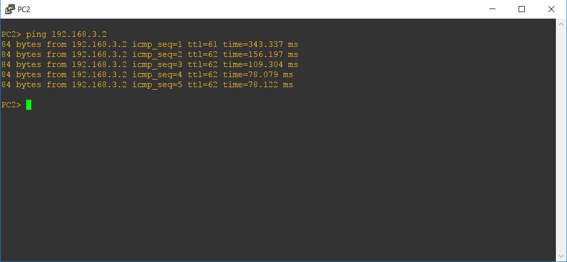
I will now go to PC2 which is located on LAN behind R3 and try to ping the PC3 which is located on LAN behind R2 router.
You can see that PC2 can ping the PC3. And now if run show crypto session command on R2 again, you will notice two sessions.
R2#show crypto session
Crypto session current status

Interface: Tunnel0
Session status: UP-ACTIVE
Peer: 202.164.1.2 port 500
 IKEv1 SA: local 202.164.1.10/500 remote 202.164.1.2/500 Active
 IPSEC FLOW: permit 47 host 202.164.1.10 host 202.164.1.2
 Active SAs: 2, origin: crypto map

Interface: Tunnel0
Session status: UP-ACTIVE
Peer: 202.164.1.6 port 500
 IKEv1 SA: local 202.164.1.10/500 remote 202.164.1.6/500 Active
 IKEv1 SA: local 202.164.1.10/500 remote 202.164.1.6/500 Active
 IPSEC FLOW: permit 47 host 202.164.1.10 host 202.164.1.6
 Active SAs: 4, origin: crypto map

R2#
First one is the permanent circuit from Hub-to-R2 (peer 202.164.1.2) and the second one is dynamically build session from R2-to-R3 (peer 102.164.1.6).
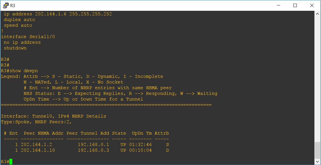
To check further, you can run show dmvpn command on either of spoke router and this time you will see 2 tunnels instead of one:
R3#show dmvpn
Legend: Attrb --> S - Static, D - Dynamic, I - Incomplete
 N - NATed, L - Local, X - No Socket
 # Ent --> Number of NHRP entries with same NBMA peer
 NHS Status: E --> Expecting Replies, R --> Responding, W --> Waiting
 UpDn Time --> Up or Down Time for a Tunnel
==========================================================================

Interface: Tunnel0, IPv4 NHRP Details
Type:Spoke, NHRP Peers:2,

# Ent Peer NBMA Addr Peer Tunnel Add State UpDn Tm Attrb
 ----- --------------- --------------- ----- -------- -----
 1 202.164.1.2 192.168.0.1 UP 01:32:46 S
 1 202.164.1.10 192.168.0.3 UP 00:10:04 D

R3#
Explanation of above output:
The Peer NBMA Addr column represents the spoke router’s public IP address.
The Peer Tunnel Add column shows each spoke router’s tunnel address.
The State column shows the current state of the tunnel. In our case, both tunnels are UP.
The UpDN Tm column is the Up or Down Time of the Tunnel’s current State.
The Attrib column shows the type of tunnels established by the spokes. D means Dynamic, S means Static. The tunnel from Hub-to-spoke router should be shown as S and tunnel from spoke-to-spoke will be shown as D since they are created dynamically.
Some more commands to check the status of VPN tunnels are given below:
- show crypto isakmp sa
HUB#show crypto isakmp sa
IPv4 Crypto ISAKMP SA
dst src state conn-id status
202.164.1.2 202.164.1.6 QM_IDLE 1005 ACTIVE
202.164.1.2 202.164.1.10 QM_IDLE 1004 ACTIVE

IPv6 Crypto ISAKMP SA

HUB#
- show crypto ipsec sa
HUB#show crypto ipsec sa

interface: Tunnel0
 Crypto map tag: Tunnel0-head-0, local addr 202.164.1.2

protected vrf: (none)
 local ident (addr/mask/prot/port): (202.164.1.2/255.255.255.255/47/0)
 remote ident (addr/mask/prot/port): (202.164.1.6/255.255.255.255/47/0)
 current_peer 202.164.1.6 port 500
 PERMIT, flags={origin_is_acl,}
 #pkts encaps: 50, #pkts encrypt: 50, #pkts digest: 50
 #pkts decaps: 38, #pkts decrypt: 38, #pkts verify: 38
 #pkts compressed: 0, #pkts decompressed: 0
 #pkts not compressed: 0, #pkts compr. failed: 0
 #pkts not decompressed: 0, #pkts decompress failed: 0
 #send errors 0, #recv errors 0

local crypto endpt.: 202.164.1.2, remote crypto endpt.: 202.164.1.6
 path mtu 1500, ip mtu 1500, ip mtu idb (none)
 current outbound spi: 0x37068F37(923176759)
 PFS (Y/N): N, DH group: none

[output cut]
This is how you can configure a DMVPN network using Cisco routers. The best part of this configuration is that it offers a resiliency to your topology. Whenever you have to add any remote site to existing topology, you only need to do a minor change to your existing routers’ configuration.


