
- July 13, 2015
- Posted by: Surender Kumar
- Category: Cisco Switches
Configure VLANs and InterVLAN Routing
Table of Contents
Configuring VLANs is pretty easy but before going into configuration, you need to plan how many VLANs you need and how to assign the users to different VLANs. Once you figure it out, you can go ahead and create the VLAN using global config vlan command.
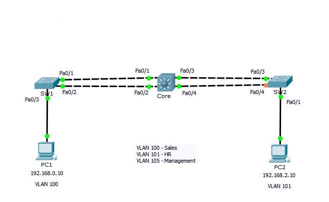 According to above sample network, we need to create 3 VLANs with the names Sales, HR and Management. I will create the VLANs on Core switch and configure it as VTP server so that it can propagate these VLANs to other switches.
So, Let’s get started.
Create VLANs
Core#conf t
Enter configuration commands, one per line.  End with CNTL/Z.
Core(config)#vlan ?
  WORD        ISL VLAN IDs 1-4094
  access-map  Create vlan access-map or enter vlan access-map command mode
  dot1q       dot1q parameters
  filter      Apply a VLAN Map
  internal    internal VLAN

Core(config)#vlan 100
Core(config-vlan)#?
name
Core(config-vlan)#name Sales
Core(config-vlan)#vlan 101
Core(config-vlan)#name HR
Core(config-vlan)#vlan 105
Core(config-vlan)#name Management
Core(config-vlan)#end
Core#
The command vlan followed by a number will create a VLAN and then name command will assign the descriptive name to VLAN, however name command is not mandatory. Now, lets take a look at VLANs on switch using show vlan command. This command will show you complete details of VLANs.
Core#show vlan

VLAN Name                             Status    Ports
---- -------------------------------- --------- -------------------------------
1    default                          active    Fa0/3, Fa0/4, Fa0/5, Fa0/6
                                                Fa0/7, Fa0/8, Fa0/9, Fa0/10
                                                Fa0/11, Fa0/12, Fa0/13, Fa0/14
                                                Fa0/15, Fa0/16, Fa0/17, Fa0/18
                                                Fa0/19, Fa0/20, Fa0/21, Fa0/22
                                                Fa0/23, Fa0/24, Gig0/1, Gig0/2
100  Sales                            active
101  HR                               active
105  Management                       active
1002 fddi-default                     act/unsup
1003 token-ring-default               act/unsup
1004 fddinet-default                  act/unsup
1005 trnet-default                    act/unsup

VLAN Type  SAID       MTU   Parent RingNo BridgeNo Stp  BrdgMode Trans1 Trans2
---- ----- ---------- ----- ------ ------ -------- ---- -------- ------ ------
1    enet  100001     1500  -      -      -        -    -        0      0
100  enet  100100     1500  -      -      -        -    -        0      0
101  enet  100101     1500  -      -      -        -    -        0      0
105  enet  100105     1500  -      -      -        -    -        0      0
1002 fddi  101002     1500  -      -      -        -    -        0      0
1003 tr    101003     1500  -      -      -        -    -        0      0
1004 fdnet 101004     1500  -      -      -        ieee -        0      0
1005 trnet 101005     1500  -      -      -        ibm  -        0      0

Remote SPAN VLANs
------------------------------------------------------------------------------


Primary Secondary Type              Ports
------- --------- ----------------- ------------------------------------------
Core#
If you want to see the brief details about VLANs, you can use show vlan brief command as shown below.
Core#show vlan brief

VLAN Name                             Status    Ports
---- -------------------------------- --------- -------------------------------
1    default                          active    Fa0/3, Fa0/4, Fa0/5, Fa0/6
                                                Fa0/7, Fa0/8, Fa0/9, Fa0/10
                                                Fa0/11, Fa0/12, Fa0/13, Fa0/14
                                                Fa0/15, Fa0/16, Fa0/17, Fa0/18
                                                Fa0/19, Fa0/20, Fa0/21, Fa0/22
                                                Fa0/23, Fa0/24, Gig0/1, Gig0/2
100  Sales                            active
101  HR                               active
105  Management                       active
1002 fddi-default                     active
1003 token-ring-default               active
1004 fddinet-default                  active
1005 trnet-default                    active
Core#
You can see the VLANs 100, 101 and 105 listed along with other VLANs that exists by default on switch and every interface is assigned to VLAN 1 by default. Remember that you cannot modify or delete default VLANs i.e. VLAN with ID 1 and 1002-1005.
VLANs are now created but each VLAN is unusable until any switchport is assigned to it. To assign an interface to VLAN, you need to go to each interface and tell it which VLAN to be a part of.
Configure Trunk Ports
You know that the trunk links are used to carry the traffic belonging to multiple VLANs. Switches SW1 and SW2 are connected to Core switch using 2 links. Now, we will configure links between these switches as Trunk.
SW1 configuration:
SW1#conf t
Enter configuration commands, one per line.  End with CNTL/Z.
SW1(config)#interface range fastEthernet 0/1-2
SW1(config-if-range)#switchport mode trunk
SW1(config-if-range)#switchport trunk native vlan 105
SW1(config-if-range)#switchport trunk allowed vlan 100-105
In above configuration commands, I have selected both fastEthernet0/1 and fastEthernet0/2 interfaces using interface range command and then the command switchport mode trunk will set these interfaces in trunk mode. The switchport trunk native vlan command sets the native vlan to 105. Remember that by-default native VLAN is 1 but we have changed native VLAN to be 105 as a security measure. By default all the VLANs are allowed through trunk ports but we can use the switchport trunk allowed vlan command to specify the vlans that are allowed through trunk ports.
SW2 configuration:
SW2#conf t
Enter configuration commands, one per line.  End with CNTL/Z.
SW2(config)#int range fa0/3-4
SW2(config-if-range)#switchport mode trunk
SW2(config-if-range)#
%LINEPROTO-5-UPDOWN: Line protocol on Interface FastEthernet0/3, changed state to down

%LINEPROTO-5-UPDOWN: Line protocol on Interface FastEthernet0/3, changed state to up

%LINEPROTO-5-UPDOWN: Line protocol on Interface FastEthernet0/4, changed state to down

%LINEPROTO-5-UPDOWN: Line protocol on Interface FastEthernet0/4, changed state to up

SW2(config-if-range)#switchport trunk native vlan 105
SW2(config-if-range)#switchport trunk allowed vlan 100-105
SW2(config-if-range)#end
SW2#
Core configuration:
Core#conf t
Enter configuration commands, one per line.  End with CNTL/Z.
Core(config-if-range)#int range fa0/3-4
Core(config-if-range)#switchport mode trunk
Command rejected: An interface whose trunk encapsulation is "Auto" can not be configured to "trunk" mode.
Command rejected: An interface whose trunk encapsulation is "Auto" can not be configured to "trunk" mode.
Core(config-if-range)#switchport trunk encapsulation dot1q
Core(config-if-range)#switchport mode trunk
Core(config-if-range)#switchport trunk native vlan 105
Core(config-if-range)#switchport trunk allowed vlan 100-105
Core(config-if-range)#int range fa0/1-2
Core(config-if-range)#switchport mode trunk
Core(config-if-range)#switchport trunk native vlan 105
Core(config-if-range)#switchport trunk allowed vlan 100-105
Core(config-if-range)#switchport trunk encapsulation dot1q
Core(config-if-range)#end
Core#
The configuration of Core switch is same as SW1 and SW2. You will notice that only switchport trunk encapsulation command is new in Core switch. This is because Core switch is Cisco 3560 which is a layer-3 switch and it supports multiple trunking methods such as ISL and dot1q as we have discussed above in VLAN Tagging Protocols section. Switches SW1 and SW2 are 2960 series switches which does not support multiple tagging methods. So, it does not give you the option to specify encapsulation type.
Now that the Trunk Links are configured. We will configure VTP on Core switch which will use trunk links to propagate VLANs to SW1 and SW2.
Configure VTP
We will configure Core switch to be VTP Server and others as client.
Core#conf t
Enter configuration commands, one per line.  End with CNTL/Z.
Core(config)#vtp ?
  domain    Set the name of the VTP administrative domain.
  mode      Configure VTP device mode
  password  Set the password for the VTP administrative domain
  version   Set the adminstrative domain to VTP version
Core(config)#vtp mode server
Device mode already VTP SERVER.
Core(config)#vtp domain techtutsonline
Changing VTP domain name from NULL to techtutsonline
Core(config)#vtp password Abc@123
Setting device VLAN database password to Abc@123
Core(config)#end
Core#
The vtp mode server command sets the switch mode as VTP server. Notice that the switch says device mode already SERVER. This is because, by default every Cisco switch is VTP server. The vtp domain command sets VTP domain name and vtp password sets the password. This is pretty straightforward.
Now, the SW1 and SW2 need to be configured as VTP client and domain name and password must be same.
Before configuring VTP on SW1, I will use show vlan brief command to make sure no other VLANs exist on this switch (except default VLANs).
SW1#show vlan brief

VLAN Name                             Status    Ports
---- -------------------------------- --------- -------------------------------
1    default                          active    Fa0/3, Fa0/4, Fa0/5, Fa0/6
                                                Fa0/7, Fa0/8, Fa0/9, Fa0/10
                                                Fa0/11, Fa0/12, Fa0/13, Fa0/14
                                                Fa0/15, Fa0/16, Fa0/17, Fa0/18
                                                Fa0/19, Fa0/20, Fa0/21, Fa0/22
                                                Fa0/23, Fa0/24, Gig0/1, Gig0/2
1002 fddi-default                     active
1003 token-ring-default               active
1004 fddinet-default                  active
1005 trnet-default                    active
SW1#
You can see there is no VLAN create yet. Now let’s go ahead and configure VTP.
SW1#conf t
Enter configuration commands, one per line.  End with CNTL/Z.
SW1(config)#vtp mode client
Setting device to VTP CLIENT mode.
SW1(config)#vtp domain techtutsonline
Changing VTP domain name from NULL to techtutsonline
SW1(config)#vtp password Abc@123
Setting device VLAN database password to Abc@123
SW1(config)#end
SW1#
Similarly on SW2
SW2#conf t
Enter configuration commands, one per line.  End with CNTL/Z.
SW2(config)#vtp mode client
Setting device to VTP CLIENT mode.
SW2(config)#vtp domain techtutsonline
Changing VTP domain name from NULL to techtutsonline
SW2(config)#vtp password Abc@123
Setting device VLAN database password to Abc@123
SW2(config)#end
SW2#
Now let’s check VLAN details once again.
SW2#show vlan brief

VLAN Name                             Status    Ports
---- -------------------------------- --------- -------------------------------
1    default                          active    Fa0/1, Fa0/2, Fa0/5, Fa0/6
                                                Fa0/7, Fa0/8, Fa0/9, Fa0/10
                                                Fa0/11, Fa0/12, Fa0/13, Fa0/14
                                                Fa0/15, Fa0/16, Fa0/17, Fa0/18
                                                Fa0/19, Fa0/20, Fa0/21, Fa0/22
                                                Fa0/23, Fa0/24, Gig0/1, Gig0/2
100  Sales                            active
101  HR                               active
105  Management                       active
1002 fddi-default                     active
1003 token-ring-default               active
1004 fddinet-default                  active
1005 trnet-default                    active
SW2#
Here we go. Did you see VLANs 100, 101 and 105 automatically created on SW2? This means VTP server has successfully propagated VLANs to SW2 and SW1.
Enable VTP Pruning
Core# configure terminal
Core(config)#vtp pruning
Pruning switched on
Core(config)#int range fa0/1-2
Core(config-if-range)#switchport trunk pruning vlan 100-105
Core(config-if-range)#end
The vtp pruning global config command is used to enable VTP pruning on switch and switchport trunk pruning vlan command is used to specify the VLANs to be pruned.
You can use show vtp status command to verify the status of VTP on switch as shown below.
SW2#show vtp status
VTP Version                     : 2
Configuration Revision          : 0
Maximum VLANs supported locally : 255
Number of existing VLANs        : 8
VTP Operating Mode              : Client
VTP Domain Name                 : techtutsonline
VTP Pruning Mode                : Enabled
VTP V2 Mode                     : Disabled
VTP Traps Generation            : Disabled
MD5 digest                      : 0x5E 0x11 0x45 0x7E 0x5A 0x73 0x55 0x3E
Configuration last modified by 192.168.1.12 at 3-1-93 00:29:40
SW2#
Now, it is time to assign switchports to specific VLANs.
Assigning Switch Ports to VLANs
You can configure each port on a switch to be in a specific VLAN by using the interface config mode switchport access vlan command. You can also configure multiple ports at the same time with the interface range command. In our sample network, PC1 and PC2 belong to VLAN 100 and VLAN 101 respectively. So, let’s assign the switchports accordingly.
SW1#conf t
Enter configuration commands, one per line.  End with CNTL/Z.
SW1(config)#interface fastEthernet 0/3
SW1(config-if)#switchport mode ?
access Set trunking mode to ACCESS unconditionally
dynamic Set trunking mode to dynamically negotiate access or trunk mode
trunk Set trunking mode to TRUNK unconditionally
SW1(config-if)#switchport mode access
SW1(config-if)#switchport access vlan 100
SW1(config-if)#
SW2#conf t
Enter configuration commands, one per line.  End with CNTL/Z.
SW2(config)#int fa0/1
SW2(config-if)#switchport mode access
SW2(config-if)#switchport access vlan 101
SW2(config-if)#
The switchport mode access command will set switchport to be access port and switchport access vlan command will set the port to be the member of respective vlan.
The options for switchport mode can be access, dynamic or trunk.
switchport mode access: This puts the interface into permanent non-trunking mode. The interface becomes a non-trunk interface regardless of whether the neighbor
interface is a trunk interface. The port would be a dedicated layer 2 port.
switchport mode dynamic auto: This mode makes the interface able to convert the link to a trunk link. The interface becomes a trunk interface if the neighbor interface is set to trunk or desirable mode. This is default mode in Cisco catalyst switches.
switchport mode dynamic desirable: This one makes the interface actively attempt to
convert the link to a trunk link. The interface becomes a trunk interface if the neighbor
interface is set to trunk, desirable, or auto mode.
switchport mode trunk: This puts the interface into permanent trunking mode and negotiates to convert the neighbor link into a trunk link. The interface becomes a trunk interface even if the neighbor interface isn’t a trunk interface.
switchport nonegotiate: This prevents the interface from generating Dynamic Trunking Protocol (DTP) frames. You can use this command only when the interface switchport mode is access or trunk. You must manually configure the neighboring interface as a trunk interface to establish a trunk link.
Configuring Inter-VLAN Routing using Router on a Stick
You have now configured VLANs, VTP and Trunk Links on all the switches in our sample network. By default, the hosts which are members of the same VLAN can communicate. To allow hosts on different VLANs to communicate, you need a layer 3 device (either a router or a layer 3 switch).
The inter-VLAN routing configuration steps are different on Router and Layer-3 switch. So, I will configure using both Router as well as Layer-3 switch.
I am going to start with the router approach first. Consider the following addressing scheme and network diagram.
PC1: 192.168.0.10, 255.255.255.0, default gateway 192.168.0.1
PC2: 192.168.2.10, 255.255.255.0, default gateway 192.168.2.1
SW1: 192.168.5.10, 255.255.255.0, default gateway 192.168.5.1
SW2: 192.168.5.11, 255.255.255.0, default gateway 192.168.5.1
Core: 192.168.5.12, 255.255.255.0, default gateway 192.168.5.1
Configure the IP address, subnet mask and default-gateway in PC1, PC2 and all the switches as shown above.
SW1(config)#int vlan 1
SW1(config-if)#no ip address
SW1(config-if)#shutdown
SW1(config-if)#
%LINK-5-CHANGED: Interface Vlan1, changed state to administratively down
SW1(config-if)#int vlan 105
%LINK-5-CHANGED: Interface Vlan105, changed state to up
%LINEPROTO-5-UPDOWN: Line protocol on Interface Vlan105, changed state to up
SW1(config-if)#ip address 192.168.5.10 255.255.255.0
SW1(config-if)#exit
SW1(config)#ip default-gateway 192.168.5.1
Remember that we are using VLAN 105 as management VLAN instead of default VLAN 1. So, we have issued shutdown command under vlan 1.
SW2#conf t
Enter configuration commands, one per line.  End with CNTL/Z.
SW2(config)#int vlan 1
SW2(config-if)#no ip address
SW2(config-if)#shut
%LINK-5-CHANGED: Interface Vlan1, changed state to administratively down
SW2(config-if)#int vlan 105
%LINK-5-CHANGED: Interface Vlan105, changed state to up
%LINEPROTO-5-UPDOWN: Line protocol on Interface Vlan105, changed state to up

SW2(config-if)#ip address 192.168.5.11 255.255.255.0
SW2(config-if)#exit
SW2(config)#ip default-gateway 192.168.5.1
Core#conf t
Enter configuration commands, one per line.  End with CNTL/Z.
Core(config)#int vlan 1
Core(config-if)#no ip add
Core(config-if)#shut
%LINK-5-CHANGED: Interface Vlan1, changed state to administratively down

%LINEPROTO-5-UPDOWN: Line protocol on Interface Vlan1, changed state to down

Core(config-if)#int vlan 105
Core(config-if)#
%LINK-5-CHANGED: Interface Vlan105, changed state to up

%LINEPROTO-5-UPDOWN: Line protocol on Interface Vlan105, changed state to up

Core(config-if)#ip add 192.168.5.12 255.255.255.0
Core(config-if)#exit
Core(config)#ip default-gateway 192.168.5.1
Because all switches are in same IP subnet, you can now verify if switches can reach each other by running ping.
PC1 and PC2 belong to different VLANs and all the switches are in separate VLAN (105)
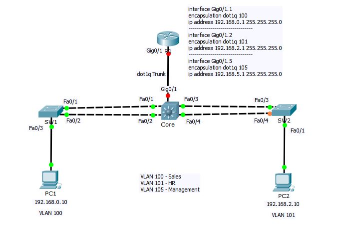 You know that Router generally has very limited number of interfaces as compared to layer-3 switch. So, we cant configure each router interface for different VLAN. Instead, we will divide the router’s one interface into logical sub-interfaces—one for each VLAN.
First, we need to configure the link between Core switch and R1 as Trunk and set the encapsulation to dot1q.
Core#conf t
Enter configuration commands, one per line.  End with CNTL/Z.
Core(config)#int gigabitEthernet 0/1
Core(config-if)#switchport trunk encapsulation dot1q
Core(config-if)#switchport mode trunk
Core(config-if)#switchport trunk native vlan 105
Core(config-if)#end
Core#
Now let’s go ahead and configure interVLAN routing on R1
R1#conf t
Enter configuration commands, one per line.  End with CNTL/Z.
R1(config)#interface gigabitEthernet 0/1.1
R1(config-subif)#encapsulation dot1Q ?
  <1-1005>  IEEE 802.1Q VLAN ID
R1(config-subif)#encapsulation dot1Q 100
R1(config-subif)#ip address 192.168.0.1 255.255.255.0
R1(config-subif)#no shutdown
R1(config-subif)#interface gigabitEthernet 0/1.2
R1(config-subif)#encapsulation dot1Q 101
R1(config-subif)#ip address 192.168.2.1 255.255.255.0
R1(config-subif)#no shutdown
R1(config-subif)#interface gigabitEthernet 0/1.5
R1(config-subif)#encapsulation dot1Q 105
R1(config-subif)#ip address 192.168.5.1 255.255.255.0
R1(config-subif)#no shutdown
R1(config-subif)#int gig0/1
R1(config-if)#no ip address
R1(config-if)#no shut
R1(config-if)#end
In above configuration commands on R1, I have create 3 logical sub-interfaces under main physical interface gigabitEthernet0/1 with the name gigabitEthernet0/1.1, gigabitEthernet0/1.2 and gigabitEthernet0/1.5 for VLAN 100, 101 and 105 respectively. The number after interface name gigabitEthernet0/1 (1, 2, 5) is arbitrary and has nothing to do with VLAN ID. The command encapsulation dot1Q followed by VLAN ID is doing the actual magic of mapping the VLAN ID with router’s sub-interface and ip address command is used to assign the IP address to sub-interface (or VLAN interface). And at the end, you have to go into main interface configuration mode (gigabitEthernet0/1) and do a no shutdown command to bring the interface up. Remember, Router’s interfaces are shutdown by default.
After above configuration, PC1 and PC2 can now communicate with each other.
PC1>ipconfig

FastEthernet0 Connection:(default port)

   Link-local IPv6 Address.........: FE80::20A:F3FF:FEC5:2282
   IP Address......................: 192.168.0.10
   Subnet Mask.....................: 255.255.255.0
   Default Gateway.................: 192.168.0.1

PC1>ping 192.168.0.1

Pinging 192.168.0.1 with 32 bytes of data:

Reply from 192.168.0.1: bytes=32 time=1ms TTL=255
Reply from 192.168.0.1: bytes=32 time=1ms TTL=255
Reply from 192.168.0.1: bytes=32 time=0ms TTL=255
Reply from 192.168.0.1: bytes=32 time=0ms TTL=255

Ping statistics for 192.168.0.1:
    Packets: Sent = 4, Received = 4, Lost = 0 (0% loss),
Approximate round trip times in milli-seconds:
    Minimum = 0ms, Maximum = 1ms, Average = 0ms

PC1>ping 192.168.2.10

Pinging 192.168.2.10 with 32 bytes of data:

Reply from 192.168.2.10: bytes=32 time=0ms TTL=127
Reply from 192.168.2.10: bytes=32 time=0ms TTL=127
Reply from 192.168.2.10: bytes=32 time=0ms TTL=127
Reply from 192.168.2.10: bytes=32 time=0ms TTL=127

Ping statistics for 192.168.2.10:
    Packets: Sent = 4, Received = 4, Lost = 0 (0% loss),
Approximate round trip times in milli-seconds:
    Minimum = 0ms, Maximum = 0ms, Average = 0ms

PC1>
In above configuration, we used a single interface of router to configure interVLAN routing. This method is also known as “router on a stick”. I also want to point out that this creates a bottleneck, as well as a single point of failure in your network. If R1 becomes unreachable due to any reason, none of your hosts will be able to communicate with hosts in different VLAN.
To mitigate this risk, you can you a layer-3 capable switch to perform inter VLAN communication.
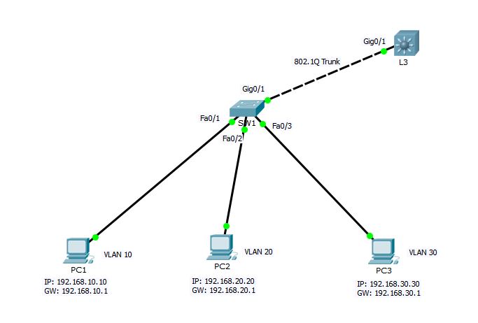
Configuring Inter-VLAN Routing using Layer-3 Switch
Cisco catalyst switches accomplish inter-vlan routing by creating Layer 3 interfaces known as Switch Virtual Interfaces (SVI). This procedure requires layer 3 switch like Catalyst 3560, 3750, 4500 4000 Series running Enhanced Multilayer Image (EMI) or Standard Multilayer Image (SMI) with IOS 12.1(11) EA1 and later.
Consider the following sample network.
 SW1 Switch Configuration
SW1#conf t
Enter configuration commands, one per line.  End with CNTL/Z.
SW1(config)#vtp mode client
Setting device to VTP CLIENT mode.
SW1(config)#vtp domain techtutsonline
Changing VTP domain name from NULL to techtutsonline
SW1(config)#vtp password Abc@123
Setting device VLAN database password to Abc@123
SW1(config)#int giga0/1
SW1(config-if)#switchport mode trunk
SW1(config-if)#end
SW1#
%SYS-5-CONFIG_I: Configured from console by console

SW1#show vlan brief

VLAN Name                             Status    Ports
---- -------------------------------- --------- -------------------------------
1    default                          active    Fa0/1, Fa0/2, Fa0/3, Fa0/4
                                                Fa0/5, Fa0/6, Fa0/7, Fa0/8
                                                Fa0/9, Fa0/10, Fa0/11, Fa0/12
                                                Fa0/13, Fa0/14, Fa0/15, Fa0/16
                                                Fa0/17, Fa0/18, Fa0/19, Fa0/20
                                                Fa0/21, Fa0/22, Fa0/23, Fa0/24
                                                Gig0/2
10   VLAN0010                         active
20   VLAN0020                         active
30   VLAN0030                         active
1002 fddi-default                     active
1003 token-ring-default               active
1004 fddinet-default                  active
1005 trnet-default                    active
SW1#conf t
Enter configuration commands, one per line.  End with CNTL/Z.
SW1(config)#interface fastEthernet 0/1
SW1(config-if)#switchport access vlan 10
SW1(config-if)#interface fastEthernet 0/2
SW1(config-if)#switchport access vlan 20
SW1(config-if)#interface fastEthernet 0/3
SW1(config-if)#switchport access vlan 30
SW1(config-if)#end
SW1#
L3 Switch Configuration
L3#config term
L3(config)#vtp mode server
Device mode already VTP SERVER.
L3(config)#vtp domain techtutsonline
Changing VTP domain name from NULL to techtutsonline
L3(config)#vtp password Abc@123
Setting device VLAN database password to Abc@123
L3(config)#vtp pruning
L3(config)#
L3(config)#int gig0/1
L3(config-if)#switchport trunk encapsulation dot1q
L3(config-if)#switchport mode trunk
L3(config-if)#exit
L3(config)#interface vlan 10
L3(config-if)#
%LINK-5-CHANGED: Interface Vlan10, changed state to up

%LINEPROTO-5-UPDOWN: Line protocol on Interface Vlan10, changed state to up

L3(config-if)#ip address 192.168.10.1 255.255.255.0
L3(config-if)#no shutdown
L3(config-if)#interface vlan 20
L3(config-if)#ip address 192.168.20.1 255.255.255.0
%LINK-5-CHANGED: Interface Vlan20, changed state to up

%LINEPROTO-5-UPDOWN: Line protocol on Interface Vlan20, changed state to up

L3(config-if)#interface vlan 30
L3(config-if)#ip address 192.168.30.1 255.255.255.0
%LINK-5-CHANGED: Interface Vlan30, changed state to up

%LINEPROTO-5-UPDOWN: Line protocol on Interface Vlan30, changed state to up

L3(config-if)#exit
L3(config)#ip routing
L3(config)#end
L3#
In L3 configuration, I have assigned IP address to each switched virtual interface (SVI). and then enabled IP routing using ip routing global mode command.
After completing above step, all the hosts PC1, PC2 and PC3 should be able to communicate among each other. Verify using ping command from PC1.
PC1>ipconfig

FastEthernet0 Connection:(default port)

   Link-local IPv6 Address.........: FE80::20D:BDFF:FE82:2509
   IP Address......................: 192.168.10.10
   Subnet Mask.....................: 255.255.255.0
   Default Gateway.................: 192.168.10.1

PC1>ping 192.168.10.1

Pinging 192.168.10.1 with 32 bytes of data:

Reply from 192.168.10.1: bytes=32 time=0ms TTL=255
Reply from 192.168.10.1: bytes=32 time=0ms TTL=255

Ping statistics for 192.168.10.1:
    Packets: Sent = 2, Received = 2, Lost = 0 (0% loss),
Approximate round trip times in milli-seconds:
    Minimum = 0ms, Maximum = 0ms, Average = 0ms

Control-C
^C
PC1>ping 192.168.30.30

Pinging 192.168.30.30 with 32 bytes of data:

Request timed out.
Reply from 192.168.30.30: bytes=32 time=0ms TTL=127
Reply from 192.168.30.30: bytes=32 time=1ms TTL=127
Reply from 192.168.30.30: bytes=32 time=0ms TTL=127

Ping statistics for 192.168.30.30:
    Packets: Sent = 4, Received = 3, Lost = 1 (25% loss),
Approximate round trip times in milli-seconds:
    Minimum = 0ms, Maximum = 1ms, Average = 0ms

PC1>
You can see that interVLAN routing is pretty easy to accomplish using Layer-3 switch as compared to that of Router. There is no need of creating sub-interfaces as we did in case of Router. Using layer-3 switch, SVI and ip routing process can do the magic of inter-VLAN communication.
This concludes the VLAN and inter-VLAN routing section.