
- July 15, 2015
- Posted by: Surender Kumar
- Category: Cisco Routers
Basics of Frame Relay
Table of Contents
Frame Relay basically is a high-performance wide area network protocol which use packet switching and operates at the physical and data link layers of the Open System Interconnection (OSI) reference model. Network providers commonly implement frame relay for voice and data as an encapsulation technique, used between local area networks (LANs) over a wide area network (WAN). Each end-user gets a private line or leased line to frame relay node. The frame relay network handles the transmission over a frequently changing path which is transparent to all end-users.
Frame Relay is considered as Non-Broadcast Multi Access (NBMA) network because it does not allow sending Layer-2 broadcasts so that all the devices in same broadcast domain can receive that broadcast.
Why Frame Relay?
Suppose that your company is expanded to two new locations. The Head Office is connected to two branch offices, and you want these two branches to communicate with the head office. The most simple solution is to connect them directly via a leased line as shown below:
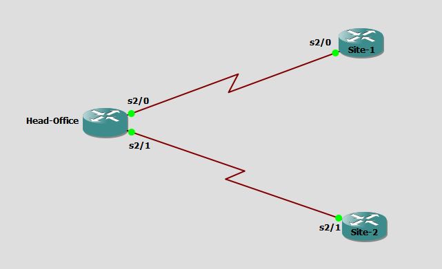 To connect two different sites, the Head-Office router requires two serial interfaces and it is very common for a router to have 2 interfaces. But what will happen if the company expands into 10 or 20 branches in different geographical locations? For each point-to-point link, Head-Office router need a separate serial interface and it is not possible to have 20 serial interfaces in a router.
In this case, you might look for something which is known as Frame Relay. In Frame Relay, we only need one serial interface at the Head-Office router to connect to all sites and the cost is much lesser as compared to that of leased-lines.
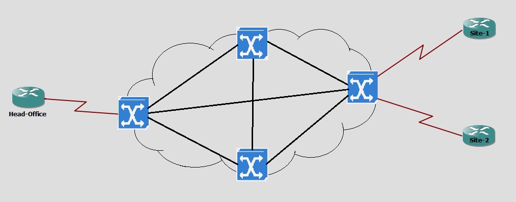 Frame relay offers lower-cost data transfer by using virtual connections and by combining those connections into a single physical connection at each location. Frame relay providers use frame relay switches to route the data on each virtual circuit to the appropriate destination.
Frame Relay Terminology
- DTE: Data Terminating Equipment is a device that converts user information into signals or reconverts received signals. It is the device connected at user end.
- DCE: Data Communication Equipment or Data circuit-terminating equipment is a device used to establish, maintain and terminate communication network sessions between a data source and its destination. Frame Relay switches work as DCE to provide clocking as well as packet switching.
- VC: Virtual Circuit is the logical connection through the Frame Relay network between two DTE devices. logical connection means that the two devices are not directly connected to each other but still have connectivity via service provider switches.
- SVC: Switched Virtual Circuit is a temporary connection that is only used when there is data transfer between DTE devices across the Frame Relay network. SVCs are set up dynamically when needed.
- PVC: Permanent Virtual Circuit is a predefined virtual circuit which offers a guaranteed bandwidth and extremely low latency for establishing a connection. Because the switching pathway is permanent, the quality of the connection does not vary with time.
- DLCI: Data Link Connection Identifier is a 10 bit long virtual circuit identifier (VC ID) used to assign frames to a specific PVC or SVC. Frame Relay networks use DLCIs to statistically switch the frames. DLCI values are locally significant like Ethernet MAC addresses which are significant in whole broadcast domain or VLAN. DLCI is considered as layer 2 address of frame relay like MAC address of Ethernet.
- LMI: Local Management Interface is a signaling standard used between routers and frame relay switches. It is responsible for managing the connection and maintaining the status of your PVC.
How Frame Relay Works
Frame-relay uses data-link connection identifier (DLCI) to build up logical circuits. The identifiers are locally significant. For example in network diagram shown below, the DLCI 102 is representing the connection from Head-Office to Site-1 and DLCI 103 is representing the connection from Head-Office to Site-2.
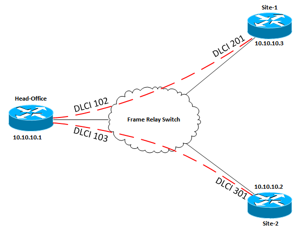 DLCI is a 10-bit number typically assigned by the Frame Relay service provider. DLCI is mapped with the IP address of its remote router before it can be used to route traffic. According to frame relay network shown above, the Head-Office router need to map Site-1 router’s IP address (10.10.10.3) to DLCI 102 and Site-2 router’s IP address (10.10.10.2) to DLCI 103. After mapping it can encapsulate data inside a Frame Relay’s frame and send to the destination. The mapping of DLCI to Layer 3 IP address can be handled manually or dynamically.
Manual Mapping: You can statically assign a DLCI to the remote IP address by using frame-relay map command as shown below:
Head-Office#config term
Head-Office(config)#int se2/0
Head-Office(config-if)#frame-relay map ip 10.10.10.3 102 broadcast
Head-Office(config-if)#frame-relay map ip  10.10.10.2 103 broadcast
Head-Office(config-if)#end
Head-Office#
The broadcast keyword is used because by default split-horizon will prevent routing updates from being sent back on the same interface as it was received.
Dynamic Mapping: The router can send an Inverse ARP Request to the other end of the PVC for its Layer 3 address. In short, Inverse ARP will attempt to learn its neighboring devices IP addresses and automatically create a dynamic map table. By default, physical interfaces have Inverse ARP enabled.
So, How inverse ARP will work in the frame relay network shown above?
At the beginning, all routers are not configured with static mapping and Head-Office router has not learned the IP addresses of Site-1 and Site-2 yet. It only has 2 DLCI values on serial interface (102 & 103). Now it needs to find out the IP address of remote routers. So, It will send an Inverse ARP Request out on every DLCI associated with the interface. When Site-1 & Site-2 receive this request, they send back an Inverse ARP Reply with their own IP addresses. By default, routers send Inverse ARP messages on all active DLCIs every 60 seconds.
Local Management Interface (LMI) is used in frame relay as a signaling protocol between DTE and the first Frame Relay switch. The LMI is responsible for managing the connection and maintaining the status of your virtual circuit. LMI uses keepalives and also reports the status of every PVCs. By default, keepalives are sent every 10 seconds and status updates are sent at every 6th keepalive (60 seconds).
When Head-Office router is configured with Frame Relay, it sends an Status Inquiry message to the DCE. The DCE device reports the status using the LMI protocol and the status can be:
- ACTIVE — The PVC is operational and can transmit packets.
- INACTIVE — The PVC is configured but down.
- DELETED — The PVC is not present (DTE device only), which means that no status is received from the LMI protocol.
- STATIC — The Local Management Interface (LMI) is disable on the interface by using no keepalive command. This status is rarely seen.
Usually, Cisco routers auto-detect the LMI type but if it is manually configured, it must match at both DCE and DTE devices. Cisco routers support ansi, cisco and q933a LMI types.
High-Level Data Link Control (HDLC), Point-to-Point Protocol (PPP) and Asynchronous Transfer Mode (ATM) etc are some other alternatives of Frame Relay. Frame Relay is a legacy technology which is now almost replaced by VPN and MPLS but still you can quite often come across to Frame Relay.
In the next section, we will look into the Frame Relay Configuration.