
- July 15, 2015
- Posted by: Surender Kumar
- Category: Cisco Routers
Frame Relay Configuration
Table of Contents
If you are not familiar with the basics of Frame Relay, I would suggest you to take a look at this page. If you already know the basics, you can go ahead and start the frame relay configuration.
The topology I am going to use to demonstrate Frame Relay configuration is given below
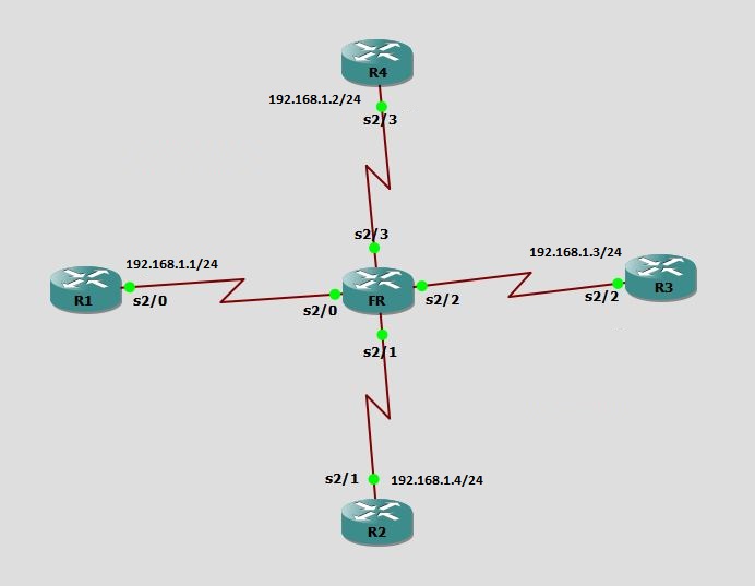
Since I am using GNS3 for this lab, I am gonna use a Router FR to simulate Frame Relay switch as shown above.
The logical topology of Frame Relay network will look as shown below:
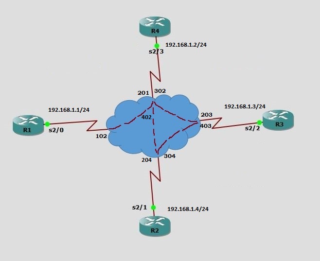
The interfaces where both customer edge devices are connected to Frame Relay Switch, are assigned a Data Link Connection Identifier (DLCI).
Frame Relay Switch Configuration
In real world, we will not have any control of frame relay switches. So, we will never have to configure frame-relay switch unless you get a chance to work with frame relay service provider. But, since we are learning frame-relay in lab environment, we are simulating a router (FR) as frame relay switch.
FR#conf t
Enter configuration commands, one per line.  End with CNTL/Z.
FR(config)#frame-relay switching
FR(config)#int se2/0
FR(config-if)#encapsulation frame-relay
FR(config-if)#frame-relay intf-type dce
FR(config-if)#clock rate 64000
FR(config-if)#frame-relay route ?
  <16-1007>  input dlci to be switched

FR(config-if)#frame-relay route 102 ?
  interface  outgoing interface for pvc switching

FR(config-if)#frame-relay route 102 inter
FR(config-if)#frame-relay route 102 interface se2/0 ?
  <16-1007>  output dlci to use when switching

FR(config-if)#frame-relay route 102 interface se2/3 201
FR(config-if)#no shut
FR(config-if)#
FR(config-if)#int se2/3
FR(config-if)#encapsulation frame-relay
FR(config-if)#frame-relay intf-type dce
FR(config-if)#clock rate 64000
FR(config-if)#frame-relay route 201 interface se2/0 102
FR(config-if)#frame-relay route 302 interface se2/2 203
FR(config-if)#frame-relay route 402 interface se2/1 204
FR(config-if)#no shutdown
FR(config-if)#
FR(config-if)#int se2/2
FR(config-if)#encapsulation frame-relay
FR(config-if)#frame-relay intf-type dce
FR(config-if)#clock rate 64000
FR(config-if)#frame-relay route 203 interface serial 2/3 302
FR(config-if)#frame-relay route 403 interface serial 2/1 304
FR(config-if)#no shutdown
FR(config-if)#
FR(config-if)#int se2/1
FR(config-if)#encapsulation frame-relay
FR(config-if)#frame-relay intf-type dce
FR(config-if)#clock rate 64000
FR(config-if)#frame-relay route 304 interface serial 2/2 403
FR(config-if)#frame-relay route 204 interface serial 2/3 402
FR(config-if)#no shut
FR(config-if)#end
FR#
The frame-relay switching global command is used to enable Frame Relay switching on Router.
The encapsulation frame-relay command enables the frame-relay process on the selected interface.
The frame-relay intf-type dce command declare the interface to be a DCE device for frame relay switching instead of DTE. By default, routers are DTE devices.
The clock rate command is required at DCE device to provide the layer 1 clocking to serial interfaces.
The frame-relay route command is essentially used in FR router’s point of view which is working as frame relay switch. For example, frame-relay route 102 interface se2/3 201 command on interface serial 2/0 is telling that router R1 having DLCI 102 is connected to Router R4 having DLCI 201 via interface Serial 2/3.
Note:- The frame-relay route command is interface mode command but there is a new version of this command which is not yet supported on all routers. This new version is global config mode command as opposed to interface mode. The syntax of command is connect [name] [input interface] [source dlci] [output interface] [destination dlci]. Both frame-relay route and connect commands achieve the same result despite of different syntax.
You can see the status of frame-relay route using show frame-relay route command as shown below
FR#show frame-relay route
Input Intf      Input Dlci      Output Intf     Output Dlci     Status
Serial2/0       102             Serial2/3       201             inactive
Serial2/1       304             Serial2/2       403             inactive
Serial2/2       203             Serial2/3       302             inactive
Serial2/2       403             Serial2/1       304             inactive
Serial2/3       201             Serial2/0       102             inactive
Serial2/3       302             Serial2/2       203             inactive
In above output, the Status is inactive because we have not configured the serial interfaces on customer end routers R1, R2, R3 and R4 yet.
Customer end Routers’ Configuration
Configure Hub (main site) Router R4:
We have configured the encapsulation as frame-relay on all the serial interfaces of FR router (frame-relay switch). By default, every serial interface on Cisco router runs HDLC encapsulation. You can verify the encapsulation using show interface serial 2/3 command as shown below.
R4#show interfaces serial2/3
Serial2/3 is administratively down, line protocol is down
  Hardware is M4T
  MTU 1500 bytes, BW 1544 Kbit, DLY 20000 usec,
     reliability 255/255, txload 1/255, rxload 1/255
  Encapsulation HDLC, crc 16, loopback not set
  Keepalive set (10 sec)

[output cut]
Line is administratively down because interface is disabled and protocol is down due to mismatch in encapsulation. one end is running HDLC (default) and other end is running frame-relay.
Now, let’s configure R4 router first because it is Hub of Frame relay network or in other words we can say R4 is the Head Office router which will be connected to all other sites.
R4#config term
R4(config)#int se2/3
R4(config-if)#encapsulation frame-relay
R4(config-if)#no shutdown
R4(config-if)#end
After changing the encapsulation and enabling the interface, you should now see the status of line/protocol as up/up.
R4#show int se2/3
Serial2/3 is up, line protocol is up
  Hardware is M4T
  MTU 1500 bytes, BW 1544 Kbit, DLY 20000 usec,
     reliability 255/255, txload 1/255, rxload 1/255
  Encapsulation FRAME-RELAY, crc 16, loopback not set
  Keepalive set (10 sec)
  Restart-Delay is 0 secs
  LMI enq sent  21, LMI stat recvd 22, LMI upd recvd 0, DTE LMI up
  LMI enq recvd 0, LMI stat sent  0, LMI upd sent  0
  LMI DLCI 1023  LMI type is CISCO  frame relay DTE
  FR SVC disabled, LAPF state down

[output cut]
The LMI type is shown as frame relay DTE which means router R4 is DTE device. Now, we will configure the IP address on interface.
R4#conf t
Enter configuration commands, one per line.  End with CNTL/Z.
R4(config)#int se2/3
R4(config-if)#ip add 192.168.1.2 255.255.255.0
R4(config-if)#end
R4#
We have already set the encapsulation and issued no shutdown command on this interface.
Configure spoke (branch) Routers R1, R2 and R3:
R1#conf t
Enter configuration commands, one per line.  End with CNTL/Z.
R1(config)#int se2/0
R1(config-if)#ip add 192.168.1.1 255.255.255.0
R1(config-if)#encapsulation frame-relay
R1(config-if)#no shut
R1(config-if)#end
R1#
R2#conf t
Enter configuration commands, one per line.  End with CNTL/Z.
R2(config)#int se2/1
R2(config-if)#encapsulation frame-relay
R2(config-if)#ip address 192.168.1.4 255.255.255.0
R2(config-if)#no shut
R2(config-if)#end
R2#
R3#conf t
Enter configuration commands, one per line.  End with CNTL/Z.
R3(config)#int se2/2
R3(config-if)#encapsulation frame-relay
R3(config-if)#ip address 192.168.1.3 255.255.255.0
R3(config-if)#no shut
R3(config-if)#end
R3#
We will not configure any IP address on FR router since it is working as frame relay switch. You have now completed the configuration of frame relay.
Verify Frame Relay Configuration
After configuration, you should see the router R4 has learned the dynamic mapping of DLCIs to Remote IP addresses because Inverse ARP is by default enabled. Let’s check the frame relay dynamic mapping on R4.
R4#show frame-relay map
Serial2/3 (up): ip 192.168.1.1 dlci 201(0xC9,0x3090), dynamic,
              broadcast,, status defined, active
Serial2/3 (up): ip 192.168.1.3 dlci 302(0x12E,0x48E0), dynamic,
              broadcast,, status defined, active
Serial2/3 (up): ip 192.168.1.4 dlci 402(0x192,0x6420), dynamic,
              broadcast,, status defined, active
You can see, R4 has learned the layer-3 IP addresses via Inverse ARP. And if we go to router R1 and check the same thing. Router R1 is saying: Hey, I know the Hub router R4 is reachable on IP 192.168.1.2 via DLCI 102.
R1#show frame-relay map
Serial2/0 (up): ip 192.168.1.2 dlci 102(0x66,0x1860), dynamic,
              broadcast,, status defined, active
Both routers R2 and R3 can reach R4 and they can also reach each other as well.
R2#show frame-relay map
Serial2/1 (up): ip 192.168.1.2 dlci 204(0xCC,0x30C0), dynamic,
              broadcast,, status defined, active
Serial2/1 (up): ip 192.168.1.3 dlci 304(0x130,0x4C00), dynamic,
              broadcast,, status defined, active
R2#
R3#show frame-relay map
Serial2/2 (up): ip 192.168.1.2 dlci 203(0xCB,0x30B0), dynamic,
              broadcast,, status defined, active
Serial2/2 (up): ip 192.168.1.4 dlci 403(0x193,0x6430), dynamic,
              broadcast,, status defined, active
R3#
If you do not want Inverse ARP to do the mapping and you want to do static mapping, you can do this by using frame-relay map command. I am going to configure static mapping on R3 router.
R3(config)#int se2/0
R3(config-if)#frame-relay map ip 192.168.1.2 203 broadcast
R3(config-if)#^Z
R3#show frame-relay map
Serial2/2 (up): ip 192.168.1.2 dlci 203(0xCB,0x30B0), static,
              CISCO, status defined, active
The frame-relay map ip 192.168.1.2 203 broadcast command configures a static mapping of DLCI 203 to IP address 192.168.1.2 on R3. You can see the keyword static in output above as opposed to dynamic.
Let us verify the Frame Relay connectivity using ping command.
R1#ping 192.168.1.2

Type escape sequence to abort.
Sending 5, 100-byte ICMP Echos to 192.168.1.2, timeout is 2 seconds:
!!!!!
Success rate is 100 percent (5/5), round-trip min/avg/max = 60/67/84 ms
R1#ping 192.168.1.3

Type escape sequence to abort.
Sending 5, 100-byte ICMP Echos to 192.168.1.3, timeout is 2 seconds:
.....
Success rate is 0 percent (0/5)
R1#ping 192.168.1.4

Type escape sequence to abort.
Sending 5, 100-byte ICMP Echos to 192.168.1.4, timeout is 2 seconds:
.....
Success rate is 0 percent (0/5)
Did you notice that R1 can reach R4 (Hub) but it can not reach R2 and R3? This is because we have not configured any Virtual Circuit on FR (frame relay switch) to these destinations. To prove this, let us enable debug on router R1 using debug ip packet and debug frame-relay packet commands and then see the debug output.
R1#debug ip packet
IP packet debugging is on
R1#debug frame-relay packet
Frame Relay packet debugging is on
R1#
After debugging is enabled on R1, run the ping to 192.168.1.3 and the ping will fail. You will see the output as shown below:
R1#ping 192.168.1.3

Type escape sequence to abort.
Sending 5, 100-byte ICMP Echos to 192.168.1.3, timeout is 2 seconds:

*Jul 16 13:19:44.903: IP: tableid=0, s=192.168.1.1 (local), d=192.168.1.3 (Serial2/0), routed via RIB
*Jul 16 13:19:44.907: IP: s=192.168.1.1 (local), d=192.168.1.3 (Serial2/0), len 100, sending
*Jul 16 13:19:44.907: Serial2/0:Encaps failed--no map entry link 7(IP)
*Jul 16 13:19:44.907: IP: s=192.168.1.1 (local), d=192.168.1.3 (Serial2/0), len 100, encapsulation failed.
*Jul 16 13:19:46.903: IP: tableid=0, s=192.168.1.1 (local), d=192.168.1.3 (Serial2/0), routed via RIB
*Jul 16 13:19:46.903: IP: s=192.168.1.1 (local), d=192.168.1.3 (Serial2/0), len 100, sending

[output cut]

Success rate is 0 percent (0/5)
In above output, the line marked Purple is due to debug frame-relay packet command and line marked Red is due to debug ip packet command. This clearly states that encapsulation is failing because there is no map entry to destination 192.168.1.3. To make communication possible between spoke to spoke, you have to create route entry on frame relay switch as we did for R2 and R3.
Router R4 can reach every site because it is hub router located in Head-Office:
R4#ping 192.168.1.1

Type escape sequence to abort.
Sending 5, 100-byte ICMP Echos to 192.168.1.1, timeout is 2 seconds:
!!!!!
Success rate is 100 percent (5/5), round-trip min/avg/max = 60/62/64 ms
R4#ping 192.168.1.3

Type escape sequence to abort.
Sending 5, 100-byte ICMP Echos to 192.168.1.3, timeout is 2 seconds:
!!!!!
Success rate is 100 percent (5/5), round-trip min/avg/max = 60/61/64 ms
R4#ping 192.168.1.4

Type escape sequence to abort.
Sending 5, 100-byte ICMP Echos to 192.168.1.4, timeout is 2 seconds:
!!!!!
Success rate is 100 percent (5/5), round-trip min/avg/max = 64/64/68 ms
R4#
Router R2 and R3 can reach each other because we have already added route entry on Frame Relay switch using frame-relay route 304 interface Serial2/2 403 command on interface serial 2/1 and frame-relay route 403 interface Serial2/1 304 command on interface serial 2/2.
R2#ping 192.168.1.3

Type escape sequence to abort.
Sending 5, 100-byte ICMP Echos to 192.168.1.3, timeout is 2 seconds:
!!!!!
Success rate is 100 percent (5/5), round-trip min/avg/max = 40/56/64 ms
R3#ping 192.168.1.4

Type escape sequence to abort.
Sending 5, 100-byte ICMP Echos to 192.168.1.4, timeout is 2 seconds:
!!!!!
Success rate is 100 percent (5/5), round-trip min/avg/max = 60/62/64 ms
Now, I am going over to Frame Relay switch (FR router) and remove the corresponding route entries for R2 to reach R3 and vice-versa.
FR#conf t
Enter configuration commands, one per line.  End with CNTL/Z.
FR(config)#interface Serial2/1
FR(config-if)#no frame-relay route 304 interface Serial2/2 403
FR(config-if)#interface Serial2/2
FR(config-if)#no frame-relay route 403 interface Serial2/1 304
FR(config-if)#^Z
Now, R2 and R3 should not be able to ping each other.
R2#ping 192.168.1.3

Type escape sequence to abort.
Sending 5, 100-byte ICMP Echos to 192.168.1.3, timeout is 2 seconds:
.....
Success rate is 0 percent (0/5)
R2#
R3#ping 192.168.1.4

Type escape sequence to abort.
Sending 5, 100-byte ICMP Echos to 192.168.1.4, timeout is 2 seconds:
.....
Success rate is 0 percent (0/5)
R3#
At the end, R4 is able to reach every spoke router (remote site) and each spoke router is able to reach R4 (head-office) but none of the spoke routers (or remote sites) can communicate with each other.
Now, what happens when you want all of your spoke site routers to communicate with each other as well?
You can either configure static mapping or you can use point-to-point sub-interface approach.
In our sample network, I am going to configure static mapping between R1 and R3 and I will use point-to-point sub-interface approach on R2.
On R3:
R3(config)#int se2/2
R3(config-if)#frame-relay map ip 192.168.1.1 203
R3(config-if)#frame-relay map ip 192.168.1.4 203
R3(config-if)#end
R3#show frame map
Serial2/2 (up): ip 192.168.1.1 dlci 203(0xCB,0x30B0), static,
              CISCO, status defined, active
Serial2/2 (up): ip 192.168.1.2 dlci 203(0xCB,0x30B0), dynamic,
              broadcast,, status defined, active
Serial2/2 (up): ip 192.168.1.4 dlci 203(0xCB,0x30B0), static,
              CISCO, status defined, active
R3#
On R1:
R1#conf t
Enter configuration commands, one per line.  End with CNTL/Z.
R1(config)#int se2/0
R1(config-if)#frame-relay map ip 192.168.1.3 102
R1(config-if)#frame-relay map ip 192.168.1.4 102
R1(config-if)#^Z
R1#show frame-relay map
Serial2/0 (up): ip 192.168.1.2 dlci 102(0x66,0x1860), dynamic,
              broadcast,, status defined, active
Serial2/0 (up): ip 192.168.1.3 dlci 102(0x66,0x1860), static,
              CISCO, status defined, active
Serial2/0 (up): ip 192.168.1.4 dlci 102(0x66,0x1860), static,
              CISCO, status defined, active
R1#ping 192.168.1.3

Type escape sequence to abort.
Sending 5, 100-byte ICMP Echos to 192.168.1.3, timeout is 2 seconds:
!!!!!
Success rate is 100 percent (5/5), round-trip min/avg/max = 80/90/96 ms
Both R1 and R3 will use same DLCI to reach R4 (Hub) as well as other spokes (remote sites).
On R2:
R2#conf t
Enter configuration commands, one per line.  End with CNTL/Z.
R2(config)#int se2/1
R2(config-if)#no ip address
R2(config-if)#int se2/1.204 point-to-point
R2(config-subif)#frame-relay interface-dlci 204
R2(config-fr-dlci)#ip address 192.168.1.4 255.255.255.0
R2(config-subif)#no shutdown
R2(config-subif)#end
I have removed IP address from main serial interface and then created a point-to-point sub-interface serial2/1.204 under main interface 2/1. Remember that sub-interface name (204) is any arbitrary value and has nothing to do with DLCI value. I have used the same name for sub-interface to make it more comfortable to remember and then IP address is assigned to this sub-interface. The frame-relay interface-dlci 204 command tells the router that this interface will use DLCI value 204 in order to reach any destination which is in same subnet.
Now, R2 can reach any of the spoke router.
R2#ping 192.168.1.1

Type escape sequence to abort.
Sending 5, 100-byte ICMP Echos to 192.168.1.1, timeout is 2 seconds:
!!!!!
Success rate is 100 percent (5/5), round-trip min/avg/max = 88/94/108 ms
R2#ping 192.168.1.2

Type escape sequence to abort.
Sending 5, 100-byte ICMP Echos to 192.168.1.2, timeout is 2 seconds:
!!!!!
Success rate is 100 percent (5/5), round-trip min/avg/max = 40/49/64 ms
R2#ping 192.168.1.3

Type escape sequence to abort.
Sending 5, 100-byte ICMP Echos to 192.168.1.3, timeout is 2 seconds:
!!!!!
Success rate is 100 percent (5/5), round-trip min/avg/max = 88/91/96 ms
Instead of creating static mapping on all the spoke routers, it is far better to use sub-interface approach to allow the communication between spoke sites.
You can not create sub-interface on router R4 (Hub router) since it is using multiple DLCI addresses to reach each spoke.
This concludes our Frame Relay configuration section