
- August 6, 2015
- Posted by: Surender Kumar
- Category: Cisco ASA
Network Address Translation in Cisco ASA
Table of Contents
Each computer and device within an IP network is assigned a unique IP address that identifies the host. Because of a shortage of public IPv4 addresses, most of these IP addresses are private, not routable anywhere outside of the private company network.
RFC 1918 defines the private IP addresses you can use internally which are not routable by internet routers. The address range is given below for all classes of IP address:
- 10.0.0.0 through 10.255.255.255
- 172.16.0.0 through 172.31.255.255
- 192.168.0.0 through 192.168.255.255
One of the main functions of NAT is to enable private IP networks to connect to the Internet. NAT replaces a private IP address with a public IP address, translating the private addresses in the internal private network into legal, routable addresses that can be used on the public Internet. In this way, NAT conserves public addresses because it can be configured to advertise at a minimum only one public address for the entire network to the outside world.
For detailed explanation on Network Address Translation and its types, go to this section.
NAT in Routed Firewall Mode
You can configure NAT on Cisco ASA in both routed and transparent firewall mode. The below diagram shows a typical NAT example in routed mode, with a private network on the inside.
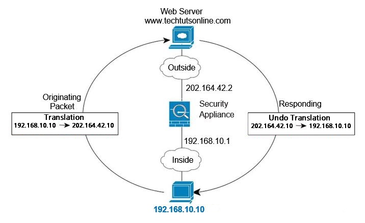
- When the inside host at 192.168.10.10 sends a packet to a web server, the real source address of the packet, 192.168.10.10, is changed to a mapped address, 202.164.42.10.
- When the server responds, it sends the response to the mapped address, 202.164.42.10, and the ASA receives the packet because the ASA performs proxy ARP to claim the packet.
- The ASA then changes the translation of the mapped address, 202.164.42.10, back to the real address, 192.168.10.10, and then send it back to the host.
NAT in Transparent Firewall Mode
Using NAT in transparent mode eliminates the need for the upstream or downstream routers to perform NAT for their networks.
- NAT in transparent mode has the following requirements and limitations:
Because the transparent firewall does not have any interface IP addresses, you cannot use interface PAT (port address translation). - ARP inspection is not supported. Moreover, if for some reason a host on one side of the ASA sends an ARP request to a host on the other side of the ASA, and the initiating host real address is mapped to a different address on the same subnet, then the real address remains visible in the ARP request.
The diagram below shows a typical NAT scenario in transparent mode, with the same network on the inside and outside interfaces. The transparent firewall in this scenario is performing the NAT service so that the upstream router does not have to perform NAT.
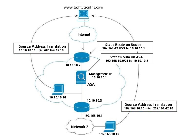
- When the inside host at 10.10.10.10 sends a packet to a web server, the real source address of the packet, 10.10.10.10, is changed to a mapped address, 202.164.42.10.
- When the server responds, it sends the response to the mapped address, 202.164.42.10, and the ASA receives the packet because the upstream router includes this mapped network in a static route directed to the ASA management IP address.
- The ASA then undoes the translation of the mapped address, 202.164.42.10, back to the real address, 10.10.10.10. Because the real address is directly-connected, the ASA sends it directly to the host.
- For host 192.168.10.10, the same process occurs, except for returning traffic, the ASA looks up the route in its routing table and sends the packet to the downstream router at 10.10.10.3 based on the ASA static route for 192.168.1.0/24.
NAT For VPN
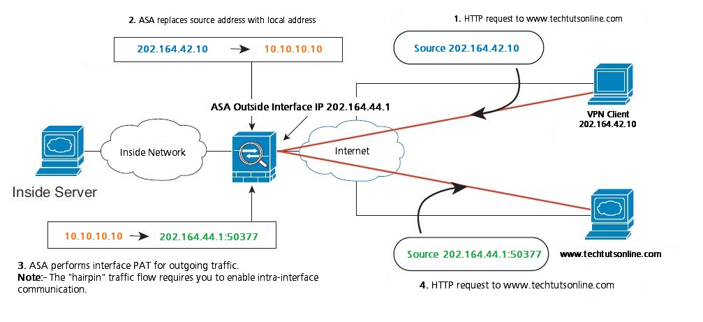
If you do not allow split-tunneling, then all VPN traffic, even traffic destined for the Internet, goes through the VPN tunnel. VPN traffic, after being decrypted by the ASA, is essentially the same as any other inside traffic: when an inside user needs to access the Internet, they need a public IP address provided by NAT.
The below network diagram shows a VPN client that wants to visit a website at www.techtutsonline.com. In this example, an interface PAT rule on the outside interface matches the VPN-assigned address 10.10.10.10. With intra-interface communication enabled, traffic can exit the same interface it entered to reach www.techtutsonline.com. A similar example without the need for hairpin networking includes an ASA for VPN termination, and a separate ASA with NAT as the Internet gateway.
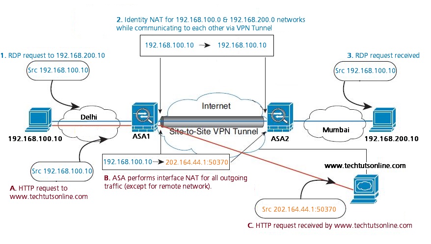
The network diagram below also shows an interface PAT rule for Internet-bound traffic. However, for any communication between VPN endpoints such as the ends of a site-to-site tunnel, you do not want to perform NAT. Therefore you also need to create an identity NAT rule (using twice NAT) for any traffic that goes to other inside networks connected by VPN.
How NAT is Implemented
The ASA can implement address translation in two ways: Network object NAT and Twice NAT.
Network Object NAT
All NAT rules that are configured as a parameter of a network object are considered to be network object NAT rules. Network object NAT is a quick and easy way to configure NAT for a network object, which can be a single IP address, a range of addresses, or a subnet.
After you configure the network object, you can then identify the mapped address for that object, either as an inline address or as another network object or network object group.
When a packet enters the ASA, both the source and destination IP addresses are checked against the network object NAT rules. The source and destination address in the packet can be translated by separate rules if separate matches are made. These rules are not tied to each other; different combinations of rules can be used depending on the traffic.
Because the rules are never paired, you cannot specify that sourceA/destinationA should have a different translation than sourceA/destinationB. Use twice NAT for that kind of functionality (twice NAT lets you identify the source and destination address in a single rule).
Twice NAT
Twice NAT lets you identify both the source and destination address in a single rule. Specifying both the source and destination addresses lets you specify that sourceA/destinationA can have a different translation than sourceA/destinationB.
The destination address is optional. If you specify the destination address, you can either map it to itself (identity NAT), or you can map it to a different address. The destination mapping is always a static mapping.
Twice NAT also lets you use service objects for static NAT with port translation; network object NAT only accepts inline definition.
The diagram below shows a host on the 10.10.10.0/24 network accessing two different Servers. When the host accesses the server at 202.164.10.10, the real address is translated to 202.164.30.10. When the host accesses the server at 202.164.20.20, the real address is translated to 202.164.30.11.

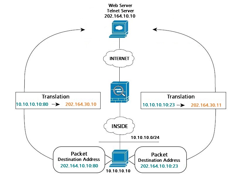
The network diagram below shows the use of source and destination ports. The host on the 10.10.10.0/24 network accesses a single Server for both web service and Telnet service. When the host accesses the server for web services, the real address is translated to 202.164.30.10. When the host accesses the same server for Telnet services, the real address is translated to 202.164.30.11.
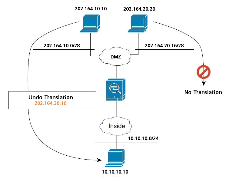
The diagram below shows a remote host connecting to a mapped host. The mapped host has a twice static NAT translation that translates the real address only for traffic to and from the 202.164.10.0/28 network. A translation does not exist for the 202.164.20.16/28 network, so the translated host cannot connect to that network, nor can a host on that network connect to the translated host.
NAT Rules Order
Network object NAT rules and twice NAT rules are stored in a single table that is divided into three sections. Section 1 rules are applied first, then section 2, and finally section 3.
The following table shows the order of rules within each section.
| Table Section | Rule Type | Order of Rules within the Section |
| Section 1 | Twice NAT | Applied on a first match basis, in the order they appear in the configuration. By default, twice NAT rules are added to section 1. Note: If you configure EasyVPN remote, the ASA dynamically adds invisible NAT rules to the end of this section. Be sure that you do not configure a twice NAT rule in this section that might match your VPN traffic, instead of matching the invisible rule. If VPN does not work due to NAT failure, consider adding twice NAT rules to section 3 instead. |
| Section 2 | Network object NAT | Section 2 rules are applied in the following order, as automatically determined by the ASA: 1. Static rules. 2. Dynamic rules. Within each rule type, the following ordering guidelines are used: a. Quantity of real IP addresses — From smallest to largest. For example, an object with one address will be assessed before an object with 10 addresses. b. For quantities that are the same, then the IP address number is used, from lowest to highest. For example, 10.1.1.0 is assessed before 11.1.1.0. c. If the same IP address is used, then the name of the network object is used, in alphabetical order. For example, abc is assessed before xyz. |
| Section 3 | Twice NAT | Section 3 rules are applied on a first match basis, in the order they appear in the configuration. You can specify whether to add a twice NAT rule to section 3 when you add the rule. |
For section 2 rules, for example, you have the following IP addresses defined within network objects:
192.168.1.0/24 (static)
192.168.1.0/24 (dynamic)
10.1.1.0/24 (static)
192.168.1.1/32 (static)
172.16.1.0/24 (dynamic) (object def)
172.16.1.0/24 (dynamic) (object abc)
The resultant ordering would be:
192.168.1.1/32 (static)
10.1.1.0/24 (static)
192.168.1.0/24 (static)
172.16.1.0/24 (dynamic) (object abc)
172.16.1.0/24 (dynamic) (object def)
192.168.1.0/24 (dynamic)
Routing NAT Packets
The ASA needs to be the destination for any packets sent to the mapped address. The ASA also needs to determine the egress interface for translated packets.
When you translate the real address to a mapped address, the mapped address you choose determines how to configure routing, if necessary, for the mapped address.See the following mapped address types:
- Addresses on the same network as the mapped interface.
If you use addresses on the same network as the mapped interface, the ASA uses proxy ARP to answer any ARP requests for the mapped addresses, thus intercepting traffic destined for a mapped address. This solution simplifies routing because the ASA does not have to be the gateway for any additional networks. This solution is ideal if the outside network contains an adequate number of free addresses, a consideration if you are using a 1:1 translation like dynamic NAT or static NAT. Dynamic PAT greatly extends the number of translations you can use with a small number of addresses, so even if the available addresses on the outside network is small, this method can be used. For PAT, you can even use the IP address of the mapped interface. - Addresses on a unique network.
If you need more addresses than are available on the mapped interface network, you can identify addresses on a different subnet. The upstream router needs a static route for the mapped addresses that points to the ASA. Alternatively for routed mode, you can configure a static route on the ASA for the mapped addresses, and then redistribute the route using your routing protocol. For transparent mode, if the real host is directly-connected, configure the static route on the upstream router to point to the ASA: in 8.3, specify the global management IP address; in 8.4(1) and later, specify the bridge group IP address. For remote hosts in transparent mode, in the static route on the upstream router, you can alternatively specify the downstream router IP address. - The same address as the real address (identity NAT).
In (8.3(1), 8.3(2), and 8.4(1)), the default behavior for identity NAT has proxy ARP disabled. You cannot configure this setting. In (8.4(2) and later), the default behavior for identity NAT has proxy ARP enabled, matching other static NAT rules. You can disable proxy ARP if desired. Note: You can also disable proxy ARP for regular static NAT if desired, in which case you need to be sure to have proper routes on the upstream router.
DNS and NAT
You might need to configure the ASA to modify DNS replies by replacing the address in the reply with an address that matches the NAT configuration. You can configure DNS modification when you configure each translation rule.
This feature rewrites the A record, or address record, in DNS replies that match a NAT rule. For DNS replies traversing from a mapped interface to any other interface, the A record is rewritten from the mapped value to the real value. Inversely, for DNS replies traversing from any interface to a mapped interface, the A record is rewritten from the real value to the mapped value.
The diagram below shows a DNS server that is accessible from the outside interface.
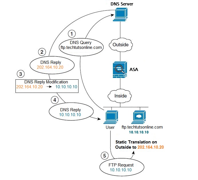
A server, ftp.techtutsonline.com, is on the inside network. You configure the ASA to statically translate the ftp.techtutsonline.com real address (10.10.10.10) to a mapped address (202.164.10.20) that is visible on the outside network. In this case, you want to enable DNS reply modification on this static rule so that inside users who have access to ftp.techtutsonline.com using the real address receive the real address from the DNS server, and not the mapped address. When an inside host sends a DNS request for the address of ftp.techtutsonline.com, the DNS server replies with the mapped address (202.164.10.20). The ASA refers to the static rule for the inside server and translates the address inside the DNS reply to 10.10.10.10. If you do not enable DNS reply modification, then the inside host attempts to send traffic to 202.164.10.20 instead of accessing ftp.techtutsonline.com directly.
Configuring Network Object NAT
When a packet enters the ASA, both the source and destination IP addresses are checked against the network object NAT rules. The source and destination address in the packet can be translated by separate rules if separate matches are made. These rules are not tied to each other; different combinations of rules can be used depending on the traffic.
Because the rules are never paired, you cannot specify that a source address should be translated to A when going to destination X, but be translated to B when going to destination Y. Use twice NAT for that kind of functionality (twice NAT lets you identify the source and destination address in a single rule).
Configuring Dynamic NAT
Step 1 Configure a network object or network object group to specify the mapped addresses (that you want to translate to). A network object group can contain objects and/or inline addresses. The object or group cannot contain a subnet.
hostname(config)# object network TEST
hostname(config-network-object)# range 10.10.10.1 10.0.10.100
Step 2 Configure a network object for which you want to configure NAT, or enter object network configuration mode for an existing network object.
hostname(config)# object network my-object1
Step 3 If you are creating a new network object, defines the real IP address(es) that you want to translate.
hostname(config-network-object)# subnet 10.10.10.0 255.255.255.0
Step 4 Configure dynamic NAT for the object IP addresses.
hostname(config-network-object)# nat (inside,outside) dynamic TEST [interface] [dns]
The interface keyword (optional) enables interface PAT fallback. After the mapped IP addresses are used up, then the IP address of the mapped interface is used. For this option, you must configure a specific interface for the mapped_ifc. (You cannot specify interface in transparent mode).
The dns keyword (optional) translates DNS replies. Be sure DNS inspection is enabled (it is enabled by default).
Configuration Examples
The following example configures dynamic NAT that hides 192.168.2.0 network behind a range of outside addresses 10.10.10.1 through 10.10.10.10:
hostname(config)# object network range-obj
hostname(config-network-object)# range 10.10.10.1 10.10.10.10
hostname(config)# object network my-inside-net
hostname(config-network-object)# subnet 192.168.2.0 255.255.255.0
hostname(config-network-object)# nat (inside,outside) dynamic range-obj
The following example configures dynamic NAT with dynamic PAT backup. Hosts on inside network 10.76.11.0 are mapped first to the nat-range1 pool (10.10.10.10 – 10.10.10.20). After all addresses in the nat-range1 pool are allocated, dynamic PAT is performed using the pat-ip1 address (10.10.10.21). In the unlikely event that the PAT translations are also use up, dynamic PAT is performed using the outside interface address.
hostname(config)# object network nat-range1
hostname(config-network-object)# range 10.10.10.10 10.10.10.20
hostname(config-network-object)# object network pat-ip1
hostname(config-network-object)# host 10.10.10.21
hostname(config-network-object)# object-group network nat-pat-grp
hostname(config-network-object)# network-object object nat-range1
hostname(config-network-object)# network-object object pat-ip1
hostname(config-network-object)# object network my_net_obj5
hostname(config-network-object)# subnet 10.76.11.0 255.255.255.0
hostname(config-network-object)# nat (inside,outside) dynamic nat-pat-grp interface
Configuring Dynamic PAT (Hide)
Step 1 Specify the mapped address(es) (that you want to translate to). You can configure a single address or, for a PAT pool, multiple addresses. Configure a network object or network object group. A network object group can contain objects and/or inline addresses. Alternatively, you can skip this step if you want to enter a single IP address as an inline value for the nat command or if you want to use the interface address by specifying the interface keyword.
hostname(config)# object network PAT_POOL1
hostname(config-network-object)# range 10.10.10.1 10.10.10.100
Step 2 Configure a network object for which you want to configure NAT, or enters object network configuration mode for an existing network object.
hostname(config)# object network my-obj1
Step 3 If you are creating a new network object, define the real IP address(es) that you want to translate.
hostname(config-network-object)# range 10.20.20.1 10.20.20.90
Step 4 Configure dynamic PAT for the object IP addresses. You can only define a single NAT rule for a given object.
hostname(config-network-object)# nat (any,outside) dynamic interface
Configuration Examples
The following example configures dynamic PAT that hides the 192.168.2.0 network behind address 10.2.2.2:
hostname(config)# object network my-inside-net
hostname(config-network-object)# subnet 192.168.2.0 255.255.255.0
hostname(config-network-object)# nat (inside,outside) dynamic 10.2.2.2
The following example configures dynamic PAT that hides the 192.168.2.0 network behind the outside interface address:
hostname(config)# object network my-inside-net
hostname(config-network-object)# subnet 192.168.2.0 255.255.255.0
hostname(config-network-object)# nat (inside,outside) dynamic interface
Configuring Static NAT or Static NAT-with-Port-Translation
Step 1 Configure a network object or network object group to specify the mapped addresses (that you want to translate to). A network object group can contain objects and/or inline addresses. Alternatively, you can skip this step if you want to enter the
IP addresses as an inline value for the nat command or if you want to use the interface address (for static NAT-with-port-translation) by specifying the interface keyword.
hostname(config)# object network PAT_POOL1
hostname(config-network-object)# range 10.10.10.1 10.10.10.100
Step 2 Configure a network object for which you want to configure NAT, or enters object network configuration mode for an existing network object.
hostname(config)# object network my-obj1
Step 3 If you are creating a new network object, define the real IP address(es) that you want to translate.
hostname(config-network-object)# range 10.20.20.1 10.20.20.90
Step 4 Configure static NAT for the object IP addresses. You can only define a single NAT rule for a given object.
hostname(config-network-object)# nat (inside,outside) static myobj1 service tcp 80 8080
Configuration Examples
The following example configures static NAT for the real host 10.1.1.1 on the inside to 10.2.2.2 on the outside with DNS rewrite enabled.
hostname(config)# object network my-host-obj1
hostname(config-network-object)# host 10.1.1.1
hostname(config-network-object)# nat (inside,outside) static 10.2.2.2 dns
The following example configures static NAT for the real host 10.1.1.1 on the inside to 2.2.2.2 on the outside using a mapped object.
hostname(config)# object network my-mapped-obj
hostname(config-network-object)# host 10.2.2.2
hostname(config-network-object)# object network my-host-obj1
hostname(config-network-object)# host 10.1.1.1
hostname(config-network-object)# nat (inside,outside) static my-mapped-obj
The following example configures static NAT-with-port-translation for 10.1.1.1 at TCP port 21 to the outside interface at port 2121.
hostname(config)# object network my-ftp-server
hostname(config-network-object)# host 10.1.1.1
hostname(config-network-object)# nat (inside,outside) static interface service tcp 21 2121
Configuring Identity NAT
Step 1 For the mapped addresses (which will be the same as the real addresses), configure a network object. Alternatively, you can skip this step if you want to enter the IP addresses as an inline value for the nat command.
hostname(config)# object network MAPPED_IPs
hostname(config-network-object)# subnet 10.1.1.0 255.255.255.0
Step 2 Configure a network object for which you want to perform identity NAT, or enters object network configuration mode for an existing network object.
hostname(config)# object network my-obj1
Step 3 If you are creating a new network object, defines the real IP address(es) to which you want to perform identity NAT. If you configured a network object for the mapped addresses in Step 1, then these addresses must match.
hostname(config-network-object)# subnet 10.1.1.0 255.255.255.0
Step 4 Configure identity NAT for the object IP addresses. You can only define a single NAT rule for a given object.
hostname(config-network-object)# nat (inside,outside) static MAPPED_IPs
Configuration Examples
The following example maps a host address to itself using an inline mapped address:
hostname(config)# object network my-host-obj1
hostname(config-network-object)# host 10.1.1.1
hostname(config-network-object)# nat (inside,outside) static 10.1.1.1
The following example maps a host address to itself using a network object:
hostname(config)# object network my-host-obj1-identity
hostname(config-network-object)# host 10.1.1.1
hostname(config-network-object)# object network my-host-obj1
hostname(config-network-object)# host 10.1.1.1
hostname(config-network-object)# nat (inside,outside) static my-host-obj1-identity
Monitoring Network Object NAT
To monitor object NAT, enter one of the following commands:
- show nat : Shows NAT statistics, including hits for each NAT rule.
- show nat pool : Shows NAT pool statistics, including the addresses and ports allocated, and how many times they were allocated.
- show running-config nat : Shows the NAT configuration.
- show xlate : Shows current NAT session information
Configuring Twice NAT
Twice NAT lets you identify both the source and destination address in a single rule. Specifying both the source and destination addresses lets you specify that a source address should be translated to A when going to destination X, but be translated to B when going to destination Y, for example.
The destination address is optional. If you specify the destination address, you can either map it to itself (identity NAT), or you can map it to a different address. The destination mapping is always a static mapping. Twice NAT also lets you use service objects for static NAT-with-port-translation; network object NAT only accepts inline definition.
Configuring Dynamic NAT
Step 1 Configure the real source addresses. You can configure either a network object or a network object group.
hostname(config)# object network MyNet
hostname(config-network-object)# subnet 10.10.10.0 255.255.255.0
If you want to translate all traffic, you can skip this step and specify the any keyword instead of creating an object or group.
Step 2 Configure the mapped source addresses. You can configure either a network object or a network object group. For dynamic NAT, you typically configure a larger group of addresses to be mapped to a smaller group. If a mapped network object contains both ranges and host IP addresses, then the ranges are used for dynamic NAT, and the host IP addresses are used as a PAT fallback.
hostname(config)# object network NAT_POOL
hostname(config-network-object)# range 202.164.10.10 202.164.10.20
Step 3 Configure the real destination addresses. You can configure either a network object or a network object group.
hostname(config)# object network Server1
hostname(config-network-object)# host 202.164.10.8
Although the main feature of twice NAT is the inclusion of the destination IP address, the destination address is optional. If you do specify the destination address, you can configure static translation for that address or just use identity NAT for it. You might want to configure twice NAT without a destination address to take advantage of some of the other qualities of twice NAT, including the use of network object groups for real addresses, or manually ordering of rules.
Step 4 Configure the mapped destination addresses. The destination translation is always static. For identity NAT, you can skip this step and simply use the same object or group for both the real and mapped addresses.
hostname(config)# object network Server1_mapped
hostname(config-network-object)# host 10.10.10.55
If you want to translate the destination address, you can configure either a network object or a network object group. The static mapping is typically one-to-one, so the real addresses have the same quantity as the mapped addresses. You can, however, have different quantities if desired.
For static interface NAT with port translation (routed mode only), you can skip this step and specify the interface keyword instead of a network object/group for the mapped address.
Step 5 Configure service objects for Destination real port and Destination mapped port. Dynamic NAT does not support port translation. However, because the destination translation is always static, you can perform port translation for the destination port. A service object can contain both a source and destination port, but only the destination port is used in this case. If you specify the source port, it will be ignored. NAT only supports TCP or UDP. When translating a port, be sure the protocols in the real and mapped service objects are identical (both TCP or both UDP).
hostname(config)# object service REAL_SVC
hostname(config-service-object)# service tcp destination eq 80
hostname(config)# object service MAPPED_SVC
hostname(config-service-object)# service tcp destination eq 8080
Step 6 Configure dynamic NAT.
hostname(config)# nat (inside,outside) source dynamic MyNet NAT_POOL
destination static Server1_mapped Server1 service MAPPED_SVC REAL_SVC
Configuring Dynamic PAT (Hide)
Step 1 Configure the real source addresses. You can configure either a network object or a network object group.
hostname(config)# object network MyNet
hostname(config-network-object)# subnet 10.10.10.0 255.255.255.0
If you want to translate all traffic, you can skip this step and specify the any keyword instead of creating an object or group.
Step 2 Specify the mapped address(es) (that you want to translate to). You can configure a single address or, for a PAT pool, multiple addresses. Configure a network object or network object group. A network object group can contain objects and/or inline addresses. Alternatively, you can skip this step if you want to enter a single IP address as an inline value for the nat command or if you want to use the interface address by specifying the interface keyword.
For mapped addresses used as a PAT pool, all addresses in the object or group, including ranges, are used as PAT addresses.
hostname(config)# object network PAT_POOL1
hostname(config-network-object)# range 10.10.10.10 10.10.10.20
hostname(config)# object network PAT_POOL2
hostname(config-network-object)# range 10.10.10.21 10.10.10.50
hostname(config)# object network PAT_IP
hostname(config-network-object)# host 10.10.10.100
hostname(config-network-object)# object-group network PAT_POOLS
hostname(config-network)# network-object object PAT_POOL1
hostname(config-network)# network-object object PAT_POOL2
hostname(config-network)# network-object object PAT_IP
Step 3 Configure the real destination addresses. You can configure either a network object or a network object group.
hostname(config)# object network Server1
hostname(config-network-object)# host 202.164.10.8
Step 4 Configure the mapped destination addresses. The destination translation is always static. For identity NAT, you can skip this step and simply use the same object or group for both the real and mapped addresses.
hostname(config)# object network Server1_mapped
hostname(config-network-object)# host 10.10.10.110
If you want to translate the destination address, you can configure either a network object or a network object group. The static mapping is typically one-to-one, so the real addresses have the same quantity as the mapped addresses. You can, however, have different quantities if desired.
Step 5 Configure service objects for Destination real port and Destination mapped port. Dynamic NAT does not support port translation. However, because the destination translation is always static, you can perform port translation for the destination port. A service object can contain both a source and destination port, but only the destination port is used in this case. If you specify the source port, it will be ignored. NAT only supports TCP or UDP. When translating a port, be sure the protocols in the real and mapped service objects are identical (both TCP or both UDP).
hostname(config)# object service REAL_SVC
hostname(config-service-object)# service tcp destination eq 80
hostname(config)# object service MAPPED_SVC
hostname(config-service-object)# service tcp destination eq 8080
Step 6 Configure dynamic PAT (Hide).
hostname(config)# nat (inside,outside) source dynamic MyNet interface destination static Server1 Server1
Configuring Static NAT or Static NAT-with-Port-Translation
Step 1 Configure the real source addresses. You can configure either a network object or a network object group.
hostname(config)# object network MyNet
hostname(config-network-object)# subnet 10.10.10.0 255.255.255.0
If you want to translate all traffic, you can skip this step and specify the any keyword instead of creating an object or group.
Step 2 Configure the mapped source addresses. You can configure either a network object or a network object group. For static NAT, the mapping is typically one-to-one, so the real addresses have the same quantity as the mapped addresses. For static interface NAT with port translation (routed mode only), you can skip this step and specify the interface keyword instead of a network object/group for the mapped address.
hostname(config)# object MyNet_mapped
hostname(config-network-object)# range 192.168.10.0 255.255.255.0
Step 3 Configure the real destination addresses. You can configure either a network object or a network object group.
hostname(config)# object network Server1
hostname(config-network-object)# host 202.164.10.8
Although the main feature of twice NAT is the inclusion of the destination IP address, the destination address is optional. If you do specify the destination address, you can configure static translation for that address or just use identity NAT for it. You might want to configure twice NAT without a destination address to take advantage of some of the other qualities of twice NAT, including the use of network object groups for real addresses, or manually ordering of rules.
Step 4 Configure the mapped destination addresses. The destination translation is always static. For identity NAT, you can skip this step and simply use the same object or group for both the real and mapped addresses.
hostname(config)# object network Server1_mapped
hostname(config-network-object)# host 10.10.10.55
If you want to translate the destination address, you can configure either a network object or a network object group. The static mapping is typically one-to-one, so the real addresses have the same quantity as the mapped addresses. You can, however, have different quantities if desired.
For static interface NAT with port translation (routed mode only), you can skip this step and specify the interface keyword instead of a network object/group for the mapped address.
Step 5 Configure service objects for:
• Source or destination real port
• Source or destination mapped port
A service object can contain both a source and destination port; however, you should specify either the source or the destination port for both service objects. You should only specify both the source and destination ports if your application uses a fixed source port (such as some DNS servers); but fixed source ports are rare. NAT only supports TCP or UDP. When translating a port, be sure the protocols in the real and mapped service objects are identical (both TCP or both UDP). For identity NAT, you can use the same service object for both the real and mapped ports.
hostname(config)# object service REAL_SRC_SVC
hostname(config-service-object)# service tcp source eq 80
hostname(config)# object service MAPPED_SRC_SVC
hostname(config-service-object)# service tcp source eq 8080
Step 6 Configure static NAT.
hostname(config)# nat (inside,dmz) source static MyNet MyNet_mapped destination static Server1 Server1 service REAL_SRC_SVC MAPPED_SRC_SVC
Configuration Example
The following example shows the use of static interface NAT with port translation. Hosts on the outside access an FTP server on the inside by connecting to the outside interface IP address with destination port 65000 through 65004. The traffic is untranslated to the internal FTP server at 192.168.10.100:6500 through :65004. Note that you specify the source port range in the service object (and not the destination port) because you want to translate the source address and port as identified in the command; the destination port is “any.” Because static NAT is bidirectional, “source” and “destination” refers primarily to the command keywords; the actual source and destination address and port in a packet depends on which host sent the packet. In this example, connections are originated from outside to inside, so the “source” address and port of the FTP server is actually the destination address and port in the originating packet.
hostname(config)# object service FTP_PASV_PORT_RANGE
hostname(config-service-object)# service tcp source range 65000 65004
hostname(config)# object network HOST_FTP_SERVER
hostname(config-network-object)# host 192.168.10.100
hostname(config)# nat (inside,outside) source static HOST_FTP_SERVER interface service FTP_PASV_PORT_RANGE FTP_PASV_PORT_RANGE
Configuring Identity NAT
Step 1 Configure the real source addresses. You can configure either a network object or a network object group. These are the addresses on which you want to perform identity NAT. If you want to perform identity NAT for all addresses, you can skip this step and instead use the keywords any any.
hostname(config)# object network MyNet
hostname(config-network-object)# subnet 10.10.10.0 255.255.255.0
Step 2 Configure the real destination addresses. You can configure either a network object or a network object group.
hostname(config)# object network Server1
hostname(config-network-object)# host 202.164.10.8
Step 3 Configure the mapped destination addresses. The destination translation is always static. For identity NAT, you can skip this step and simply use the same object or group for both the real and mapped addresses.
hostname(config)# object network Server1_mapped
hostname(config-network-object)# host 10.10.10.55
Step 4 Configure service objects for:
• Source or destination real port
• Source or destination mapped port
A service object can contain both a source and destination port; however, you should specify either the source or the destination port for both service objects. You should only specify both the source and destination ports if your application uses a fixed source port (such as some DNS servers); but fixed source ports are rare. NAT only supports TCP or UDP. When translating a port, be sure the protocols in the real and mapped service objects are identical (both TCP or both UDP). For identity NAT, you can use the same service object for both the real and mapped ports. The “not equal” (neq) operator is not supported.
hostname(config)# object service REAL_SRC_SVC
hostname(config-service-object)# service tcp source eq 80
hostname(config)# object service MAPPED_SRC_SVC
hostname(config-service-object)# service tcp source eq 8080
Step 5 Configure identity NAT.
hostname(config)# nat (inside,outside) source static MyNet MyNet destination static Server1 Server1
Monitoring Twice NAT
To monitor twice NAT, enter one of the following commands:
- show nat : Shows NAT statistics, including hits for each NAT rule.
- show nat pool : Shows NAT pool statistics, including the addresses and ports allocated, and how many times they were allocated.
- show xlate : Shows current NAT session information.
REAL WORLD EXAMPLE
Allow Telnet to internal Router from Internet
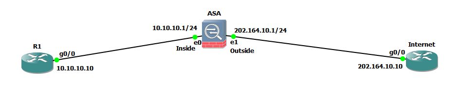
Consider that you are working as a network administrator for a company and the company has an office at remote location. The company has Router R1 connected to ASA and the ASA is connected to Internet as shown in network diagram below.
 You want Router R1 to be accessible using telnet over Internet. Although Telnet is very insecure protocol and it should not be used over internet but I am just going to use it for demonstration purpose. In real world, you can use the same method to allow your internal WebServer or FTP server to be accessible from Internet.
In this example, I am using RFC 1918 private address space for Inside network and public address for Outside network. Remember that if you are trying this in real network, then public routers will not be able to route the packets to router R1 since it is using address 10.10.10.10 which is a private address according to RFC 1918.
Let us start the configuration from R1.
R1#conf t
Enter configuration commands, one per line.  End with CNTL/Z.
R1(config)#int gig0/0
R1(config-if)#ip address 10.10.10.10 255.255.255.0
R1(config-if)#no shut
R1(config-if)#exit
R1(config)#ip route 0.0.0.0 0.0.0.0 10.10.10.1
R1(config)#exit
I have configured default route on R1 so that it will forward all the traffic to the Inside interface of ASA since ASA is working in Router mode. Now, let us move to Internet Router and configure it.
If you are working with real network, you need not to configure anything on Internet Router. But for demonstration purpose I will assume that the Internet router is just a PC connected to Internet. I will disable IP routing on this router and set it to use a default gateway like every end devices do.
Internet#conf t
Enter configuration commands, one per line.  End with CNTL/Z.
Internet(config)#int gig0/0
Internet(config-if)#ip address 202.164.10.10 255.255.255.0
Internet(config-if)#no shut
Internet(config-if)#exit
Internet(config)#no ip routing
Internet(config)#ip default-gateway 202.164.10.1
Internet(config)#^Z
Internet#
Make sure that R1 can reach its gateway (10.10.10.1).
 R1#ping 10.10.10.1

Type escape sequence to abort.
Sending 5, 100-byte ICMP Echos to 10.10.10.1, timeout is 2 seconds:
.!!!!
Success rate is 80 percent (4/5), round-trip min/avg/max = 64/72/92 ms
Internet Router should also be able to reach ASA’s Outside interface since it is configured with public IP address (202.164.10.1).
Internet#ping 202.164.10.1

Type escape sequence to abort.
Sending 5, 100-byte ICMP Echos to 202.164.10.1, timeout is 2 seconds:
!!!!!
Success rate is 100 percent (5/5), round-trip min/avg/max = 60/65/72 ms
Internet#ping 10.10.10.10

Type escape sequence to abort.
Sending 5, 100-byte ICMP Echos to 10.10.10.10, timeout is 2 seconds:
.....
Success rate is 0 percent (0/5)
This router can not ping R1 since it is behind the ASA and it is using RFC 1918 address.
Now, let us configure static NAT on ASA so that anyone can access R1 from Internet using telnet. Interface configuration of ASA is given below:
interface GigabitEthernet0
 nameif inside
 security-level 100
 ip address 10.10.10.1 255.255.255.0
!
interface GigabitEthernet1
 nameif outside
 security-level 0
 ip address 202.164.10.1 255.255.255.0
NAT configuration on ASA requires 4 steps:
- Create the network object for R1
- Create NAT statement
- Create an access-list to permit traffic flow from Outside to Inside.
- Apply the access-list on Outside interface for inbound traffic.
1. Create the network object for R1
ASA(config)# object network MyRemoteRouter
ASA(config-network-object)# host 10.10.10.10
ASA(config-network-object)#
2. Create NAT statement
The NAT statement must be created inside network object we have created in previous step.
ASA(config)# object network MyRemoteRouter
ASA(config-network-object)# nat (inside,outside) static interface service tcp 23 23
The interface keyword used in above command specifies that the IP address configured on interface will be used as mapped IP address. The first use of 23 identifies the originating port number for telnet and the second use of 23 identifies the destination port number for telnet (23).
3. Create an access-list to permit traffic flow from Outside to Inside.
By default, ASA only allow traffic to be passed from Higher security level to lower security level. This means traffic can flow from inside to outside but not in reverse direction. But in our case, we are trying to allow traffic originating from Outside to Inside. So, we need to create an access-list.
ASA(config)# access-list OutsideToR1 extended permit tcp any host 10.10.10.10 eq 23
The access-list contains just one line which defines that any host from outside (Internet) will be permitted towards particular host with address 10.10.10.10 for telnet traffic only.
Let us view the configuration on ASA:
ASA(config)# show running-config | begin object
object network MyRemoteRouter
 host 10.10.10.10
access-list OutsideToR1 extended permit tcp any host 10.10.10.10 eq telnet
pager lines 24
mtu inside 1500
mtu outside 1500
icmp unreachable rate-limit 1 burst-size 1
no asdm history enable
arp timeout 14400
!
object network MyRemoteRouter
 nat (inside,outside) static interface service tcp telnet telnet

[output cut]
Notice that ASA automatically replaced 23 with keyword telnet in running-config.
4. Apply the access-list on Outside interface for inbound traffic.
Now it is time to apply the access-list on outside interface and the access-list will be placed for inbound traffic.
ASA(config)# access-group OutsideToR1 in interface outside
Verify NAT
Now, let us go to Internet Router and try to telnet R1. Remember that you can not try telnet 10.10.10.10 because internet routers will not route the packets to private addresses. So, you have to telnet using public IP address which is assigned to Outside interface on ASA which is 202.164.10.1 in our case.
Internet#telnet 202.164.10.1
Trying 202.164.10.1 ... Open

User Access Verification

Password: *****
R1>enable
Password: *****
R1#
Don’t get confused here that you are connecting to ASA using telnet. I have not enabled telnet on ASA. The ASA will silently translate the telnet request to R1 and you will get connected to R1 using vty. The R1# prompt indicates that you are now logged-in into R1 and you can start managing the router over Internet.
R1#who
    Line       User       Host(s)              Idle       Location
   0 con 0                idle                 00:03:22
*  2 vty 0                idle                 00:00:00 202.164.10.10
As I have already told that Telnet is an insecure protocol as it does not encrypt the commands while they are sent across. You should only use SSH for managing Routers, Switches and ASA over Internet. You can use this guide to allow your internal WebServer or even FTP server to be accessible over Internet. Don’t forget to replace the port number 23 with port number 80 and 443 if you want to allow outside users to access your internal WebServer.