
- June 24, 2015
- Posted by: Surender Kumar
- Category: Cisco Routers
Dynamic Routing
Table of Contents
Dynamic routing or adaptive routing, describes the capability of a system through which routes are dynamically changed according to change in network. In dynamic routing, routing protocols are used to find networks and update routing tables on routers.
This is more scalable as compared to static routing because whenever there is any change in network or some router goes down, the routing table will be updated automatically. But in case of static routing, administrator has to manually change the route on each router.
Routing Protocols
A routing protocol is a protocol or set of rules used by routers when they communicate and exchange the routing information among neighboring routers.
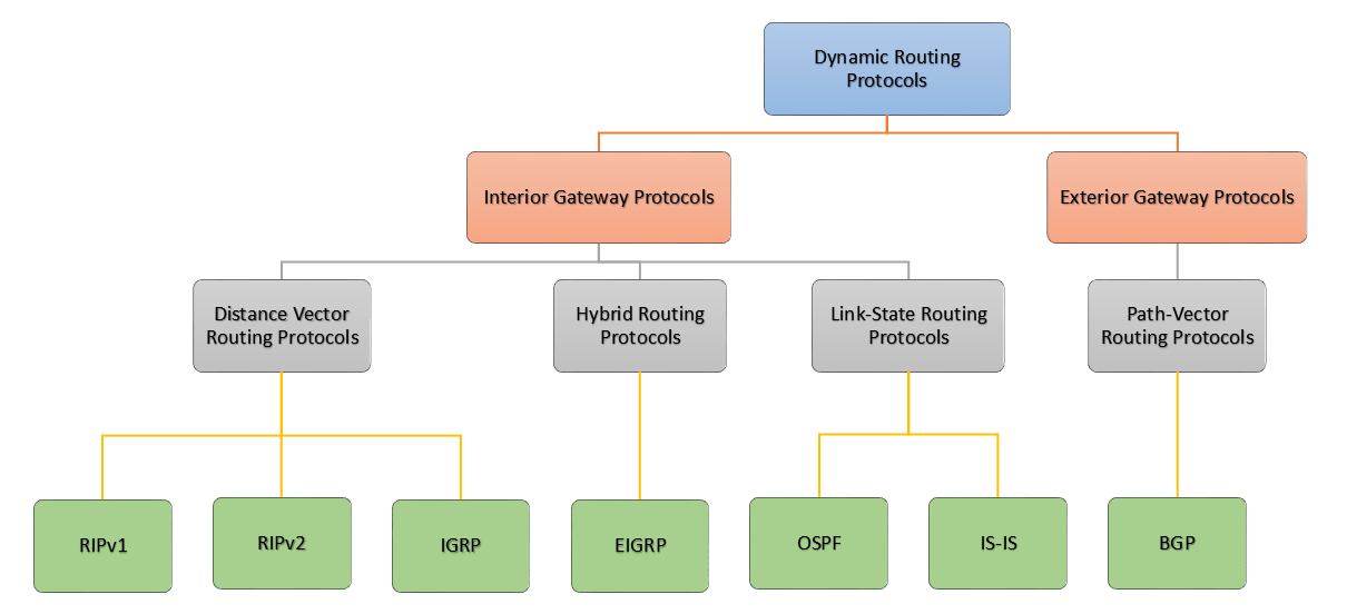
Routing Protocols can be classified according to their:
- Behavior: Classful or classless protocol
- Purpose: Interior Gateway Protocol (IGP) or Exterior Gateway Protocol (EGP)
- Operation: Distance-vector, link-state, path-vector protocol and hybrid.
Classification according to Behavior
- Classful Routing Protocols do not send subnet mask information when a route update is sent out to neighbor. All devices in the network must use the same subnet mask. Examples are RIPv1 and IGRP.
- Classless Routing Protocols have a field to send subnet mask information along with the routing updates. Classless routing protocols allows the use of VLSM. Examples are RIPv2, EIGRP and OSPF.
Classification according to Purpose
- Interior Gateway Protocols (IGPs) which are used to exchange routing information with routers in the same autonomous system (AS). Autonomous System is a collection of routers under the common administration. Examples are RIP, EIGRP, OSPF etc.
- Exterior Gateway Protocols (EGPs) which are used to exchange routing information between different autonomous systems. Example is Border Gateway Protocol (BGP).
Classification according to Operation
- Distance Vector Protocols: The distance-vector protocol finds the best path to a remote network by judging distance. Distance vector means that routes are advertised by providing two characteristics. First is Distance which identifies how far the destination network is and is based on a metric such as the hop count. Second is Vector which specifies the direction of the next-hop router or exit interface to reach the destination. In distance vector protocols the entire routing table is periodically sent to directly connected neighbors. RIPv1, RIPv2, IGRP are the examples of distance vector protocols.
- Link-State Protocols: Routers configured with link-state routing protocols can create a complete map or topology of the network by gathering information from all of the other routers. In its topology map, each router is like a node and each node then independently calculates the next best logical path from it to every possible destination in the network. The collection of best paths will then form the router’s routing table. Examples are OSPF and IS-IS.
- Hybrid Protocols: Hybrid Routing Protocol (HRP) or Balanced Hybrid Routing (BHR) is a routing protocol that combines the features of Distance Vector and Link State Routing Protocols. HRP is used to determine optimal network destination routes and report network topology data modifications. Example of hybrid protocol is EIGRP.
Routing Protocols Terminology
Administrative Distance
The administrative distance (AD) is used to determine the trustworthiness of routing information received on a router from a neighboring router. An administrative distance is an integer from 0 to 255, where 0 is the most trusted and 255 is worst route.
If a router receives two updates for the same remote network, the router will check the AD and the route with the lowest AD will be placed in the routing table.
Below table lists the default AD value for different sources:
| Default AD | Route Source |
| 0 | Connected interface |
| 1 | Static route |
| 90 | EIGRP |
| 100 | IGRP |
| 110 | OSPF |
| 120 | RIP |
| 170 | External EIGRP |
| 255 | Unknown (this route will never be used) |
Routing Loop
A routing loop is a situation where a packet keeps getting routed between two or more routers because of problems in the routing table. In case of distance vector protocols, because these protocols route by rumor and have a slow convergence time can cause routing loops because all routers are not updated simultaneously.
Consider the following scenario:
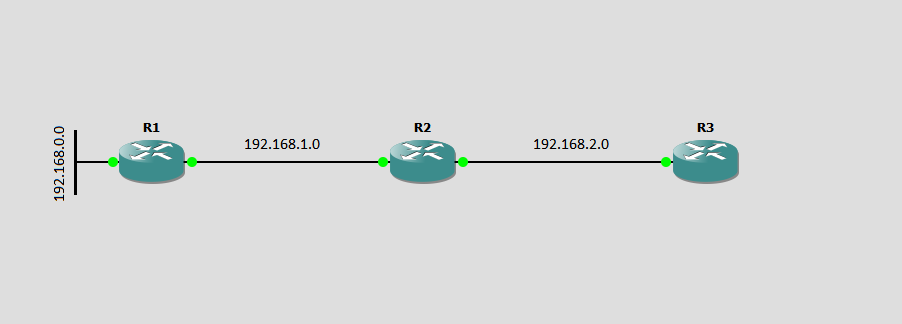
In above network, Let us assume that at any point of time all the routers R1, R2 and R3 has up to date routing table. In distance vector routing protocols, whole routing table is sent to its neighbors whether any changes occurred in the network or not. Now suppose that the link to 192.168.0.0 goes down. It means 192.168.0.0 is now not reachable. But at the same time R2 and R3 still think that 192.168.0.0 is live and reachable via R1. Because R1 and R2 did not get any update regarding link failure yet. When link 192.168.0.0 goes down, router R1 will wait for its periodic timer to expire, so that R1 can update routing information to their neighbors. Consider that 10 seconds are remaining to expire periodic timer on R1 and only 5 seconds are remaining to expire periodic timer on R2. As soon as R2 timer expires, R2 will broadcast it’s routing table along with network 192.168.0.0 (in reality, it is unreachable). R1 will also receive this update, so R1 will assume that network 192.168.0.0 is now up and reachable via R2. R1 will update its routing table with 192.168.0.0 having hop count 1. This is known as routing by rumor. As soon as R1 periodic timer will expire, R1 will broadcast the routing table along with network 192.168.0.0 with metric 1. R2 will receive update and maintain 192.168.0.0 with metric 2. And it will continue on and on causing a loop. R1 assumes that R2 has 192.168.0.0 and R2 assumes that R1 has 192.168.0.0.
How to prevent Routing Loops
The routing loop problem can be disastrous as unnecessary traffic can eat up the precious network bandwidth. There are some techniques which can be used to prevent routing loops.
- Maximum Hop Count : Defining a maximum hop count can solve infinity loop problem. RIP permits a hop count of up to 15, so anything that requires 16 hops is
will be considered as unreachable. In our sample network as shown above, after a loop of 15 hops, the network 192.168.0.0 will be considered down. Thus the maximum hop count will control how long it takes for a routing table entry to become invalid. - Split Horizon : Split-horizon is a method of preventing routing loops in distance-vector routing protocols by prohibiting a router from advertising a route back onto the interface from which it was learned. Thus when a device that participates in such route advertisements receives an update from an interface, it does not forward updates through the same interface. So, the routing loops are prevented.
- Route Poisoning : Route poisoning is a method of preventing a network from sending packets through a route that has become invalid. When the routing protocol detects an invalid route, all of the routers in the network are informed that the bad route has a hop count of 16, which stands for infinity. This prevent any of the routers from sending packets over the invalid route.
- Holddown Timer: Holddown timer works by having each router start a timer when they first receive information about a network that is unreachable. Until the timer expires, the router will discard any subsequent route messages that indicate the route is in fact reachable. Holddown prevents regular updates from reinstating a route that is going up and down (flapping). Basically, this happens on serial links losing connectivity and then coming back up. If it is not stabilized by any means, the network would never converge.
Routing Information Protocol (RIP)
RIP is a distance-vector classful routing protocol which sends the complete routing table out to all active interfaces every 30 seconds. It uses hop count to determine the best way to a remote network and it has a maximum allowable hop count of 15 by default.
RIP works well in small networks but it becomes inefficient in the networks with large number of routers installed.
The older version of RIP (RIPv1) is a classful routing protocol which means it does not have any field to advertise subnet information in its routing update. So, the networks using RIPv1 must use same subnet mask for all devices.
The later version of RIP (RIPv2) sends the subnet mask information along with routing updates. That is why it is known as classless routing protocol.
RIP Timers
The routing information protocol uses 4 different timers as part of its operation:
- Update Timer: The update timer (default 30 seconds) controls the interval between two updates in which router broadcasts its complete copy of routing table out to all RIP enabled interfaces.
- Invalid Timer: It determines the length of time (180 seconds) before a router assumes that a route has become invalid.
- Flush Timer: Flush timer controls the time between the route is invalidated, marked unreachable and removal of entry from the routing table. By default the value is 240 seconds. This is 60 seconds longer than Invalid timer. So for 60 seconds the router will be advertising about this unreachable route to all its neighbors. This timer must be set to a higher value than the invalid timer.
- Holddown Timer: Holddown timer is started per route entry, when the hop count is changing from lower value to higher value. This allows the route to get stabilized. Routes will enter into the holddown state when an update packet is received indicating the route is unreachable. This continues either until an update packet is received with a better metric, the original route comes back up, or the holddown timer expires. The default is 180 seconds.
Configuring RIP
Configuring routing is pretty straight forward as compared to theory behind their working. To configure RIP, you can use router rip command in global config mode.
Now remind this network diagram once again.
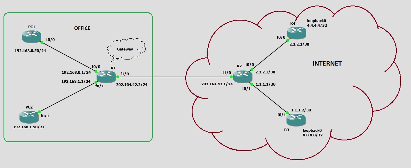
You have already configured static and dynamic routes on these routers. As you know, RIP has default AD of 120 and static route has default AD of 1 but while configuring static routes in static routing section, we have set the AD value of 150 for every route.
The reason for changing AD value of static routes to 150 is that we can configure routing protocols without manually removing static routes from routers and the RIP routes (being AD value of 120) will automatically override and remove static routes from routing table. And in case if the RIP routes becomes invalid (due to any reason), our static routes will come back into routing table and our network will still keep working. In this way our static routes are working as backup.
Now lets go to router R1 and start configuring RIP.
Enter configuration commands, one per line.  End with CNTL/Z.
R1(config)#router rip
R1(config-router)#network 202.164.42.0
R1(config-router)#network 192.168.0.0
R1(config-router)#network 192.168.1.0
R1(config-router)#end
R1#
*Jun 26 12:22:42.591: %SYS-5-CONFIG_I: Configured from console by console
R1#
In above configuration steps, you can see how easy is dynamic routing as compared to static routes. After running router rip command, the router prompt changes to R1(config-router)# which indicates you are now working in Routing protocol config mode. In this mode, the network command tells the routing protocol to advertise the networks connected to its specific interfaces. If you do not want the router to send RIP updates out of interface FastEthernet0/0; you can use passive-interface FastEthernet0/0 command. The interface will not send RIP updates but can still receive updates.
Since none of other routers are configured with RIP yet. So you will not see any RIP route in R1’s routing table but as soon as you configure RIP on neighbor routers as well, you will see the routes.
Now let’s jump over to Router R2 and configure RIP:
R2#show ip route
[output cut]

Gateway of last resort is not set

     1.0.0.0/30 is subnetted, 1 subnets
C       1.1.1.0 is directly connected, FastEthernet0/1
     2.0.0.0/30 is subnetted, 1 subnets
C       2.2.2.0 is directly connected, FastEthernet0/0
     4.0.0.0/32 is subnetted, 1 subnets
S       4.4.4.0 [150/0] via 2.2.2.2
     8.0.0.0/32 is subnetted, 1 subnets
S       8.8.8.8 [150/0] via 1.1.1.2
S    192.168.0.0/24 [150/0] via 202.164.42.2
S    192.168.1.0/24 [150/0] via 202.164.42.2
C    202.164.42.0/24 is directly connected, FastEthernet1/0
R2#
R2#conf t
Enter configuration commands, one per line.  End with CNTL/Z.
R2(config)#router rip
R2(config-router)#network 202.164.42.0
R2(config-router)#network 1.1.1.0
R2(config-router)#network 2.2.2.0
R2(config-router)#end
R2#
*Jun 26 12:29:07.019: %SYS-5-CONFIG_I: Configured from console by console
R2#show ip route
Codes: C - connected, S - static, R - RIP, M - mobile, B - BGP
[output cut]

Gateway of last resort is not set

     1.0.0.0/30 is subnetted, 1 subnets
C       1.1.1.0 is directly connected, FastEthernet0/1
     2.0.0.0/30 is subnetted, 1 subnets
C       2.2.2.0 is directly connected, FastEthernet0/0
     4.0.0.0/32 is subnetted, 1 subnets
S       4.4.4.0 [150/0] via 2.2.2.2
     8.0.0.0/32 is subnetted, 1 subnets
S       8.8.8.8 [150/0] via 1.1.1.2
R    192.168.0.0/24 [120/1] via 202.164.42.2, 00:00:19, FastEthernet1/0
R    192.168.1.0/24 [120/1] via 202.164.42.2, 00:00:19, FastEthernet1/0
C    202.164.42.0/24 is directly connected, FastEthernet1/0
R2#
Before enabling RIP on R2, I run show ip route command to list routing table. You can see that there are static routes with AD value 150.
After enabling RIP, you can see the lines marked green shows the RIP routes starting with letter R. R indicates that it is a RIP route with administrative distance of 120. Did you notice how static routes are automatically replaced by RIP routes? Well this happened because static routes had AD value 150 and RIP routes has AD value of 120 by default. So, the router will keep routes with lower AD value in its routing table and discards the routes with higher AD value (150).
Now lets enable RIP on R3 and R4 as well:
R3:
R3#conf t
Enter configuration commands, one per line.  End with CNTL/Z.
R3(config)#router rip
R3(config-router)#network 1.1.1.0
R3(config-router)#network 8.8.8.0
R3(config-router)#end
R3#show ip route
[output cut]

Gateway of last resort is not set

     1.0.0.0/30 is subnetted, 1 subnets
C       1.1.1.0 is directly connected, FastEthernet0/1
     2.0.0.0/8 is variably subnetted, 2 subnets, 2 masks
S       2.2.2.0/30 [150/0] via 1.1.1.1
R       2.0.0.0/8 [120/1] via 1.1.1.1, 00:00:08, FastEthernet0/1
     4.0.0.0/8 is variably subnetted, 2 subnets, 2 masks
S       4.4.4.4/32 [150/0] via 1.1.1.1
R       4.0.0.0/8 [120/1] via 1.1.1.1, 00:00:05, FastEthernet0/1
     8.0.0.0/32 is subnetted, 1 subnets
C       8.8.8.8 is directly connected, Loopback0
R    192.168.0.0/24 [120/1] via 1.1.1.1, 00:00:08, FastEthernet0/1
R    192.168.1.0/24 [120/1] via 1.1.1.1, 00:00:09, FastEthernet0/1
R    202.164.42.0/24 [120/1] via 1.1.1.1, 00:00:09, FastEthernet0/1
R3#
R4:
R4#conf t
Enter configuration commands, one per line.  End with CNTL/Z.
R4(config)#router rip
R4(config-router)#network 2.2.2.0
R4(config-router)#network 4.4.4.0
R4(config-router)#end
R4#show ip route
[output cut]

Gateway of last resort is not set

     1.0.0.0/8 is variably subnetted, 2 subnets, 2 masks
S       1.1.1.0/30 [150/0] via 2.2.2.1
R       1.0.0.0/8 [120/1] via 2.2.2.1, 00:00:25, FastEthernet0/0
     2.0.0.0/30 is subnetted, 1 subnets
C       2.2.2.0 is directly connected, FastEthernet0/0
     4.0.0.0/32 is subnetted, 1 subnets
C       4.4.4.4 is directly connected, Loopback0
     8.0.0.0/8 is variably subnetted, 2 subnets, 2 masks
S       8.8.8.8/32 [150/0] via 2.2.2.1
R       8.0.0.0/8 [120/1] via 2.2.2.1, 00:00:25, FastEthernet0/0
R    192.168.0.0/24 [120/1] via 2.2.2.1, 00:00:25, FastEthernet0/0
R    192.168.1.0/24 [120/1] via 2.2.2.1, 00:00:25, FastEthernet0/0
R    202.164.42.0/24 [120/1] via 2.2.2.1, 00:00:25, FastEthernet0/0
R4#
Finally, all routes showing in the routing table are RIP injected routes. Remember, How important is the Administrative Distance. Router will give priority to routes having lower AD.
R1#ping 8.8.8.8

Type escape sequence to abort.
Sending 5, 100-byte ICMP Echos to 8.8.8.8, timeout is 2 seconds:
!!!!!
Success rate is 100 percent (5/5), round-trip min/avg/max = 40/71/96 ms
R1#
You can see that our network is still working but this time with RIP routes.
Routing Information Protocol version 2 (RIPv2)
RIPv2 is a classless routing protocol, which means it can send the subnet mask
information along with the route updates. By sending the subnet mask information with the updates, it supports VLSM as well as route summarization. Other major difference between RIPv1 and RIPv2 is that RIPv2 uses multicast address during advertisements and RIPv1 uses simple broadcasts.
Configuring RIPv2
Configuration of RIPv2 is almost same as RIPv1 with except version 2 command under routing protocol config mode (config-router)# prompt as shown below.
R1#conf t
Enter configuration commands, one per line.  End with CNTL/Z.
R1(config)#router rip
R1(config-router)#network 192.168.0.0
R1(config-router)#network 192.168.1.0
R1(config-router)#network 202.164.42.0
R1(config-router)#version 2
R1(config-router)#end
R1#
*Jun 26 14:21:38.059: %SYS-5-CONFIG_I: Configured from console by console
R1#
Similarly, configure RIPv2 on R2, R3 and R4:
R2(config)#router rip
R2(config-router)#network 202.164.42.0
R2(config-router)#network 2.2.2.0
R2(config-router)#network 1.1.1.0
R2(config-router)#version 2
R2(config-router)#^Z
R2#
R3(config)#router rip
R3(config-router)#network 1.1.1.0
R3(config-router)#network 8.8.8.0
R3(config-router)#version 2
R3(config-router)#end
R3#
R4#conf t
Enter configuration commands, one per line.  End with CNTL/Z.
R4(config)#router rip
R4(config-router)#network 2.2.2.0
R4(config-router)#network 4.4.4.0
R4(config-router)#version 2
R4(config-router)#end
R4#
Verify RIP Configuration
After you have done configuring RIP, you can use show ip protocols command to view the status of RIP.
R1#show ip protocols
Routing Protocol is "rip"
  Outgoing update filter list for all interfaces is not set
  Incoming update filter list for all interfaces is not set
  Sending updates every 30 seconds, next due in 16 seconds
  Invalid after 180 seconds, hold down 180, flushed after 240
  Redistributing: rip
  Default version control: send version 2, receive version 2
    Interface             Send  Recv  Triggered RIP  Key-chain
    FastEthernet0/0       2     2
    FastEthernet0/1       2     2
    FastEthernet1/0       2     2
  Automatic network summarization is in effect
  Maximum path: 4
  Routing for Networks:
    192.168.0.0
    192.168.1.0
    202.164.42.0
  Routing Information Sources:
    Gateway         Distance      Last Update
    202.164.42.1         120      00:06:09
  Distance: (default is 120)

R1#
If you experience any issue with your network, you can always use debug command in privileged EXEC mode but keep in mind that debug command consume much resources (CPU cycles and memory). So, it is not recommended to use debug command on production networks however in case of any issue, you can use it for troubleshooting purpose. Since IOS logging messages are only sent to Console by default, therefore before running debug command if you are connected to router via telnet or ssh, then use terminal monitor command.
The debug ip rip command will display each and every routing update sent or received by router.
R1#debug ip rip
RIP protocol debugging is on
R1#
*Jun 26 14:56:17.899: RIP: sending v2 update to 224.0.0.9 via FastEthernet1/0 (202.164.42.2)
*Jun 26 14:56:17.899: RIP: build update entries
*Jun 26 14:56:17.903:   192.168.0.0/24 via 0.0.0.0, metric 1, tag 0
*Jun 26 14:56:17.903:   192.168.1.0/24 via 0.0.0.0, metric 1, tag 0
R1#
*Jun 26 14:56:21.603: RIP: sending v2 update to 224.0.0.9 via FastEthernet0/1 (192.168.1.1)
*Jun 26 14:56:21.603: RIP: build update entries
*Jun 26 14:56:21.603:   1.0.0.0/8 via 0.0.0.0, metric 1, tag 0
*Jun 26 14:56:21.607:   2.0.0.0/8 via 0.0.0.0, metric 1, tag 0
*Jun 26 14:56:21.607:   4.0.0.0/8 via 0.0.0.0, metric 1, tag 0
*Jun 26 14:56:21.607:   8.0.0.0/8 via 0.0.0.0, metric 1, tag 0
*Jun 26 14:56:21.607:   192.168.0.0/24 via 0.0.0.0, metric 1, tag 0
*Jun 26 14:56:21.611:   202.164.42.0/24 via 0.0.0.0, metric 1, tag 0
R1#
*Jun 26 14:56:23.187: RIP: sending v2 update to 224.0.0.9 via FastEthernet0/0 (192.168.0.1)
*Jun 26 14:56:23.187: RIP: build update entries
*Jun 26 14:56:23.187:   1.0.0.0/8 via 0.0.0.0, metric 1, tag 0
*Jun 26 14:56:23.191:   2.0.0.0/8 via 0.0.0.0, metric 1, tag 0
*Jun 26 14:56:23.191:   4.0.0.0/8 via 0.0.0.0, metric 1, tag 0
*Jun 26 14:56:23.191:   8.0.0.0/8 via 0.0.0.0, metric 1, tag 0
*Jun 26 14:56:23.191:   192.168.1.0/24 via 0.0.0.0, metric 1, tag 0
*Jun 26 14:56:23.195:   202.164.42.0/24 via 0.0.0.0, metric 1, tag 0
R1#
*Jun 26 14:56:27.155: RIP: received v2 update from 202.164.42.1 on FastEthernet1/0
*Jun 26 14:56:27.155:      1.0.0.0/8 via 0.0.0.0 in 1 hops
*Jun 26 14:56:27.159:      2.0.0.0/8 via 0.0.0.0 in 1 hops
*Jun 26 14:56:27.159:      4.0.0.0/8 via 0.0.0.0 in 1 hops
*Jun 26 14:56:27.159:      8.0.0.0/8 via 0.0.0.0 in 1 hops
R1#
*Jun 26 14:56:43.575: RIP: sending v2 update to 224.0.0.9 via FastEthernet1/0 (202.164.42.2)
*Jun 26 14:56:43.575: RIP: build update entries
*Jun 26 14:56:43.579:   192.168.0.0/24 via 0.0.0.0, metric 1, tag 0
*Jun 26 14:56:43.579:   192.168.1.0/24 via 0.0.0.0, metric 1, tag 0
R1#no debug ip rip
RIP protocol debugging is off
R1#
You can see above output from debug output. Carefully looking into the output may help you resolve any issues related to routing protocols configuration.
Once you have done troubleshooting your issue, you can disable debug by using no debug ip rip command.
Because of limitations in RIPv1 and RIPv2, these protocols are not recommend for modern networks. But since RIP is open standard protocol, so you can use it on any vendor Router like IBM, Asus, HP etc.
Enhanced Interior Gateway Routing Protocol (EIGRP)
EIGRP is a classless, enhanced distance-vector routing protocol. It is also referred to as a hybrid routing protocol because it has characteristics of both distance-vector and link-state protocols. Originally, it was developed to be a Cisco proprietary protocol but in March 2013, Cisco declared it as open standard protocol in order to help companies operate in a multi-vendor environment.
EIGRP Metric: EIGRP can use a composite metric to calculate the best path. It uses 4 properties to calculate metric which are:
- Bandwidth
- Delay of line
- Reliability
- Load
By default, EIGRP uses Bandwidth and delay to determine the best path to remote network.
EIGRP is a powerful routing protocol having many features. Main features are highlighted below:
- EIGRP supports multiple routed protocols like IPv4, IPv6, AppleTalk and IPX/SPX etc.
- It is a classless routing protocol means it supports VLSM, Route summarization and discontiguous networks.
- It uses Reliable Transport Protocol (RTP) for sending and receiving routing updates.
- It uses Diffusing Update Algorithm (DUAL) for best path selection which guarantees loop-free paths and backup paths throughout the network.
- EIGRP (by default) provides equal-cost load balancing across up to 4 links. But you can actually load-balance across up to 16 equal or unequal links.
EIGRP Terminology
- Feasible Distance: Feasible distance or FD is the best metric along a path to a destination network, including the metric to the neighbor advertising that path. The route with the lowest FD is considered as the best path, So it is placed in the routing table.
- Reported Distance: Reported distance or Advertised distance (AD) is the total metric along a path to a destination network as advertised by an upstream neighbor.
- Topology Table: Topology table contains all destinations advertised by neighboring routers. The advertised metric is recorded for each neighbor. This metric is stored by neighbors in their routing table.
- Successor: A successor route is the best route to a remote network. It is used by EIGRP to forward traffic to a destination and is stored in the routing table.
- Feasible Successor: A feasible Successor is a path whose Advertised Distance (AD) is less than the Feasible Distance (FD) of the current successor.
It is considered as a backup route. EIGRP will keep up to 16 feasible successors in the topology table and only one with the best metric is copied and placed in the routing table. - Neighbor Table: The neighbor table holds the information about adjacent neighbors. When newly discovered neighbors are learned, the address and interface of the neighbor is stored in neighbor table.
- Reliable Transport Protocol (RTP): Reliable Transport Protocol (RTP) manages the communication of EIGRP packets. EIGRP uses class D address 224.0.0.0 while sending update messages and it maintains a list of neighbors who have replied. If EIGRP does not get reply from a neighbor, it will try using unicast to resend the same data. If it still does not get a reply after 16 unicast attempts, the neighbor is declared dead. Routers keep track of the information they send by assigning a sequence number to each packet which helps them to detect the arrival of old, redundant or out-of-sequence information.
- Diffusing Update Algorithm (DUAL): EIGRP uses Diffusing Update Algorithm (DUAL) for selecting and maintaining the best path to each remote network. It helps EIGRP to calculate and create routing tables to determine whether a path is looped or loop-free. It also allows a router running EIGRP to find alternate paths without waiting on updates from other routers
-
Autonomous System: EIGRP uses autonomous system (AS) numbers to identify the collection of routers that share route information. The routers with same autonomous system numbers only share routing information.
Configuring EIGRP
To start an EIGRP on our routers, use the router eigrp command followed by the autonomous system number for your network. You then enter the network numbers connected to the router using the network command followed by the network number.
Let’s enable EIGRP for autonomous system 10 in our sample network shown below:
Configure R1:
R1#conf t
Enter configuration commands, one per line.  End with CNTL/Z.
R1(config)#router eigrp 10
R1(config-router)#network 202.164.42.0 0.0.0.255
R1(config-router)#network 192.168.0.0 0.0.0.255
R1(config-router)#network 192.168.1.0 0.0.0.255
R1(config-router)#no auto-summary
R1(config-router)#end
R1#
*Jun 29 14:36:07.195: %SYS-5-CONFIG_I: Configured from console by console
R1#
In above configuration steps:
router eigrp is used to enable EIGRP on router and 10 is autonomous system number. It can be any number from 1 to 65535 provided that all the Routers should use same number in order to exchange routing information.
The network statement is similar to that of RIP but in case of EIGRP we have given what is known as wildcard mask (0.0.0.255). Wildcard mask is just opposite of subnet mask. The quick and easy way to calculate the wildcard mask is to subtract the subnet mask from 255.255.255.255. Quick example to calculate wildcard mask:
For subnet mask 255.255.255.224 (/27), the wildcard mask is 0.0.0.31. See how?
Simply subtract each octet value from 255.
255 255 255 255-255 . 255 . 255 . 224 -----------------------0 . 0 . 0 . 31
R2#conf t
Enter configuration commands, one per line.  End with CNTL/Z.
R2(config)#router eigrp 10
R2(config-router)#network 202.164.42.0 0.0.0.255
*Jun 29 14:42:54.411: %DUAL-5-NBRCHANGE: IP-EIGRP(0) 10: Neighbor 202.164.42.2 (FastEthernet1/0) is up: new adjacency
R2(config-router)#network 1.1.1.0 0.0.0.3
R2(config-router)#network 2.2.2.0 0.0.0.3
R2(config-router)#no auto-summary
R2(config-router)#end
R2#
*Jun 29 14:43:37.539: %SYS-5-CONFIG_I: Configured from console by console
R2#
We have similarly configured EIGRP on R2 as well. But have you noticed something interesting after running network 202.164.42.0 0.0.0.255 command? Well, the router gives a console message %DUAL-5-NBRCHANGE: (marked green) which indicates that EIGRP protocol has found a new neighbor and added it as adjacency.
Configure R3:
R3#conf t
Enter configuration commands, one per line.  End with CNTL/Z.
R3(config)#router eigrp 10
R3(config-router)#network 1.1.1.0 0.0.0.3
R3(config-router)#
*Jun 29 14:45:56.875: %DUAL-5-NBRCHANGE: IP-EIGRP(0) 10: Neighbor 1.1.1.1 (FastEthernet0/1) is up: new adjacency
R3(config-router)#network 8.8.8.8 0.0.0.0
R3(config-router)#no auto-summary
R3(config-router)#end
R3#
Configure R4:
R4#conf t
Enter configuration commands, one per line.  End with CNTL/Z.
R4(config)#router eigrp 10
R4(config-router)#network 4.4.4.4 0.0.0.0
R4(config-router)#network 2.2.2.0 0.0.0.3
R4(config-router)#
*Jun 29 14:47:57.579: %DUAL-5-NBRCHANGE: IP-EIGRP(0) 10: Neighbor 2.2.2.1 (FastEthernet0/0) is up: new adjacency
R4(config-router)#no auto-summary
*Jun 29 14:48:03.787: %DUAL-5-NBRCHANGE: IP-EIGRP(0) 10: Neighbor 2.2.2.1 (FastEthernet0/0) is resync: summary configured
R4(config-router)#end
R4#
Let’s take a look at the routing table after configuring EIGRP on routers R1, R2, R3 and R4.
R2#
R2#show ip route
Codes: C - connected, S - static, R - RIP, M - mobile, B - BGP
       D - EIGRP, EX - EIGRP external, O - OSPF, IA - OSPF inter area
[output cut]
Gateway of last resort is not set

     1.0.0.0/30 is subnetted, 1 subnets
C       1.1.1.0 is directly connected, FastEthernet0/1
     2.0.0.0/30 is subnetted, 1 subnets
C       2.2.2.0 is directly connected, FastEthernet0/0
     4.0.0.0/8 is variably subnetted, 3 subnets, 2 masks
D       4.4.4.4/32 [90/156160] via 2.2.2.2, 00:02:33, FastEthernet0/0
S       4.4.4.0/32 [150/0] via 2.2.2.2
R       4.0.0.0/8 [120/1] via 2.2.2.2, 00:00:10, FastEthernet0/0
     8.0.0.0/8 is variably subnetted, 2 subnets, 2 masks
D       8.8.8.8/32 [90/156160] via 1.1.1.2, 00:05:15, FastEthernet0/1
R       8.0.0.0/8 [120/1] via 1.1.1.2, 00:00:15, FastEthernet0/1
D    192.168.0.0/24 [90/30720] via 202.164.42.2, 00:12:48, FastEthernet1/0
D    192.168.1.0/24 [90/30720] via 202.164.42.2, 00:12:48, FastEthernet1/0
C    202.164.42.0/24 is directly connected, FastEthernet1/0
R2#
The routes indicated by D means EIGRP (DUAL) routes.
Did you notice that after configuring EIGRP, our RIP routes have also been removed automatically?
Yes! This is due to the fact that EIGRP routes has lower Administrative Distance (90) as compared to RIP (120). Therefore, EIGRP routes override RIP routes.
Verify Network Connectivity
You can verify that the network is still working by running ping to 8.8.8.8 from R1.
R1#ping 8.8.8.8

Type escape sequence to abort.
Sending 5, 100-byte ICMP Echos to 8.8.8.8, timeout is 2 seconds:
!!!!!
Success rate is 100 percent (5/5), round-trip min/avg/max = 64/66/68 ms
R1#
Verify EIGRP Configuration
You can verify the status of EIGRP by running different commands like show ip protocols, show ip eigrp neighbors and show ip eigrp topology.
- show ip protocols
R2#show ip protocols
Routing Protocol is "rip"
  Outgoing update filter list for all interfaces is not set
  Incoming update filter list for all interfaces is not set
  Sending updates every 30 seconds, next due in 15 seconds
  Invalid after 180 seconds, hold down 180, flushed after 240
  Redistributing: rip
  Default version control: send version 2, receive version 2
    Interface             Send  Recv  Triggered RIP  Key-chain
    FastEthernet0/0       2     2
    FastEthernet0/1       2     2
    FastEthernet1/0       2     2
  Automatic network summarization is in effect
  Maximum path: 4
  Routing for Networks:
    1.0.0.0
    2.0.0.0
    202.164.42.0
  Routing Information Sources:
    Gateway         Distance      Last Update
    2.2.2.2              120      00:00:01
    1.1.1.2              120      00:00:23
    202.164.42.2         120      00:00:25
  Distance: (default is 120)

Routing Protocol is "eigrp 10"
  Outgoing update filter list for all interfaces is not set
  Incoming update filter list for all interfaces is not set
  Default networks flagged in outgoing updates
  Default networks accepted from incoming updates
  EIGRP metric weight K1=1, K2=0, K3=1, K4=0, K5=0
  EIGRP maximum hopcount 100
  EIGRP maximum metric variance 1
  Redistributing: eigrp 10
  EIGRP NSF-aware route hold timer is 240s
  Automatic network summarization is not in effect
  Maximum path: 4
  Routing for Networks:
    1.1.1.0/30
    2.2.2.0/30
    202.164.42.0
  Routing Information Sources:
    Gateway         Distance      Last Update
    2.2.2.2               90      00:15:54
    (this router)         90      00:25:34
    1.1.1.2               90      00:15:54
    202.164.42.2          90      00:15:55
  Distance: internal 90 external 170

R2#
You can still see RIP under show ip protocols because we have not disabled RIP yet, means RIP routes will reappear in routing table automatically if EIGRP faces any issue during neighbor discovery.
- show ip eigrp neighbors
R2#show ip eigrp neighbors
IP-EIGRP neighbors for process 10
H   Address                 Interface       Hold Uptime   SRTT   RTO  Q  Seq
                                            (sec)         (ms)       Cnt Num
2   2.2.2.2                 Fa0/0             13 00:19:01  391  2346  0  7
1   1.1.1.2                 Fa0/1             13 00:22:54  126   756  0  11
0   202.164.42.2            Fa1/0             13 00:29:10  114   684  0  14
R2#
where
-H indicates the order in which the neighbor was discovered.
-The hold time is how long this router will wait for a Hello packet to arrive from a specific neighbor.
-The uptime is how long the adjacency has been established.
-The SRTT field is the smooth round-trip timer. It indicates the time it takes for a round-trip from this router to its neighbor and back.
-The Retransmission Time Out (RTO) field indicated the amount of time EIGRP waits before retransmitting a packet from the retransmission queue to a neighbor.
-The Q value indicates whether there are any outstanding messages in the queue. If you see consistently large values, it means there is a problem with your EIGRP configuration.
-The Seq field indicates the sequence number of the last update from that neighbor.
- show ip eigrp topology
R2#show ip eigrp topology
IP-EIGRP Topology Table for AS(10)/ID(202.164.42.1)

Codes: P - Passive, A - Active, U - Update, Q - Query, R - Reply,
       r - reply Status, s - sia Status

P 4.4.4.4/32, 1 successors, FD is 156160
        via 2.2.2.2 (156160/128256), FastEthernet0/0
P 8.8.8.8/32, 1 successors, FD is 156160
        via 1.1.1.2 (156160/128256), FastEthernet0/1
P 1.1.1.0/30, 1 successors, FD is 28160
        via Connected, FastEthernet0/1
P 2.2.2.0/30, 1 successors, FD is 28160
        via Connected, FastEthernet0/0
P 202.164.42.0/24, 1 successors, FD is 28160
        via Connected, FastEthernet1/0
P 192.168.0.0/24, 1 successors, FD is 30720
        via 202.164.42.2 (30720/28160), FastEthernet1/0
P 192.168.1.0/24, 1 successors, FD is 30720
        via 202.164.42.2 (30720/28160), FastEthernet1/0
R2#
show ip eigrp topology command is used to see the EIGRP topology table on router.If you see P before every route in topology tables, it means your network is stable and fully converged. A indicates that the router has lost one of its path to this network and is searching for a replacement route. You can also check Feasible Distance (FD) and the Advertised Distance (AD) to a remote network.
Open Shortest Path First (OSPF)
OSPF is a link-state open standard routing protocol which works by using the Dijkstra algorithm. Dijkstra’s algorithm is an algorithm for finding the shortest paths between nodes in a graph. A shortest path tree is constructed and then the routing table is populated with the resulting best paths.
Features of OSPF:
- Efficient Updates: When an OSPF router first discovers a new neighbor, it sends a full update with all known link-state information. All routers within an OSPF area must have identical and synchronized link-state information in their OSPF link-state databases. When an OSPF network is fully converged and a new link comes up or goes down, the OSPF router sends only a partial update to all its neighbors. This update will then be flooded to all OSPF routers within an area.
- Efficient Transport: OSPF uses multicasts and unicasts, rather than broadcasts, for sending messages. The multicast addresses used for OSPF are 224.0.0.5 to send information to all OSPF routers and 224.0.0.6 to send information to DR/BDR routers.
- Metric: OSPF uses a metric that is based on the cumulative costs of all outgoing interfaces from source to destination. The interface cost is inversely proportional to the interface bandwidth.
- Authentication: It supports clear-text, MD5, and SHA authentication.
- VLSM support: OSPF is a classless routing protocol means it supports VLSM and discontiguous networks. It carries subnet mask information in the routing updates.
- Manual Route Summarization: OSPF does not support auto-summarization. However, you can manually summarize OSPF inter-area routes at the Area Border Router (ABR), and you can also summarize OSPF external routes at the Autonomous System Boundary Router (ASBR).
OSPF Terminology
- Link: A link is a network or router interface assigned to any given network. When an interface is added to the OSPF process, it is considered to be a link by OSPF.
- Router ID: The Router ID (RID) is an IP address used to identify the router. Router ID is chosen by using the highest IP address of all configured loopback interfaces. OSPF will choose the highest IP address of all active physical interfaces if no loopback interfaces are configured on router.
- Neighbor: Neighbors are two or more routers that have an interface on a common network, For example, two routers connected on via point-to-point serial link are considered as Neighbors.
- Adjacency: An adjacency is a relationship between two OSPF routers that permits the direct exchange of routing information. Unlike EIGRP, which directly shares routes with all of its neighbors, OSPF directly shares routes only with neighbors that have also established adjacency.
- Link State Advertisement: A Link State Advertisement (LSA) is an OSPF data packet containing link-state and routing information which is shared among OSPF neighbors that have established adjacency.
- Hello Protocol: Hello protocol provides dynamic neighbor discovery and maintains neighbor relationships. Hello packets and LSAs build and maintain the topological database. Hello packets are addressed to multicast address 224.0.0.5.
- Neighborship Database: The neighborship database is a list of all OSPF routers for which Hello packets have been seen. A variety of details, including the Router ID and state are maintained on each router in the neighborship database.
- Topological Database The topological database contains information from all of the LSA packets that have been received for an area. Router uses the information from the topology database as input into the Dijkstra algorithm that computes the shortest path to every network.
- Designated Router: Designated Router (DR) is elected whenever OSPF routers are connected to the same multi-access network like Ethernet. The DR is selected based on the router priority. In case of tie, the router with the highest router ID is selected.
- Backup Designated Router: A Backup Designated Router (BDR) is a hot standby for the DR on multi-access (broadcast) networks. The BDR receives all routing updates from adjacent routers but does not send LSA updates.
- OSPF Area: An OSPF area is a grouping of contiguous networks and routers. All routers in the same area share a common Area ID. A router can be a member of more than one area at a time, the Area ID is associated with specific interfaces on the router. This allows some interfaces to belong to area 1 while the remaining interfaces can belong to area 0. OSPF areas are used to establish a hierarchical network.
- Multi-access (broadcast): Multi-access (broadcast) networks such as Ethernet allow multiple devices to connect to (or access) the same network as well as provide a broadcast ability in which a single packet is delivered to all nodes on the network. In OSPF, a DR and a BDR must be elected for each broadcast multi-access network.
- Point-to-point: This configuration eliminates the need for DR and BDR. Point-to-point refers to a type of network topology consisting of a direct connection between two routers that provides a single communication path. The point-to-point connection can be physical, as in a serial cable directly connecting two routers or it can be logical as two routers that are thousands of miles apart yet connected by a circuit in a Frame Relay network.
- Point-to-multipoint: Point-to-multipoint refers to a type of network topology consisting of a series of connections between a single interface on one router and multiple destination routers. All of the interfaces on all of the routers sharing the point-to-multipoint connection belong to the same network.
- Non-Broadcast Multi-Access: NBMA are networks like Frame Relay and ATM. While these networks allow for multiple-access they do not have any broadcast capabilities like Ethernet. Special consideration is required when configuring an NBMA network with OSPF.
- Area Border Router: An Area Border Router (ABR) is a router that has interfaces assigned to more than one area. An interface can only be assigned to one area but a router may have mutiple interfaces. If the interfaces are assigned to different areas then the router is considered an ABR.
- Autonomous System Boundary Router: ASBR is a router with interface(s) connected to an external network or different AS. An example would be an interface connected to an EIGRP Autonomous Network.
OSPF Metric: OSPF uses a metric referred to as cost. A cost is associated with every outgoing interface included in an SPF tree. The cost of the entire path is the sum of the costs of the outgoing interfaces along the path. Cisco uses a simple equation of 108/bandwidth. The bandwidth is the configured bandwidth for the interface. Using this rule, a 100Mbps interface would have a default OSPF cost of 1 and a 10Mbps Ethernet interface would have a cost of 10. However, the cost can be adjusted by using ip ospf cost command.
Configuring OSPF
Configuring basic OSPF is not as simple as configuring RIP and EIGRP. But I will help you get stared by basic single-area OSPF configuration.
Let’s now begin the configuration of Area 0 OSPF configuration in our sample network.
Before starting OSPF configuration, we have to remove EIGRP. But Why?
Well ! This is because OSPF has default Administrative Distance (AD) of 110 whereas EIGRP has 90. It means OSPF routes can not automatically replace the EIGRP routes.
To disable EIGRP, I will run no router eigrp 10 and to disable RIP use no router rip command in global config mode on all routers.
R1#conf t
Enter configuration commands, one per line.  End with CNTL/Z.
R1(config)#no router eigrp 10
R1(config)#no router rip
*Jun 30 15:47:03.283: %DUAL-5-NBRCHANGE: IP-EIGRP(0) 10: Neighbor 202.164.42.1 (FastEthernet1/0) is down: interface down
R1(config)#^Z
R1#
After running command, you will immediately notice a console message saying Neighbor is down.
The OSPF can be enabled by using router ospf <process ID> command where <process ID> is not much important as in case of EIGRP. In OSPF, process ID is any arbitrary value and it is locally significant. You can use any number between 1-65535.
Configure R1:
R1#conf t
Enter configuration commands, one per line.  End with CNTL/Z.
R1(config)#router ospf ?
  <1-65535>  Process ID

R1(config)#router ospf 20
R1(config-router)#network 202.164.42.0 0.0.0.255 area 0
R1(config-router)#network 192.168.0.0 0.0.0.255 area 0
R1(config-router)#network 192.168.1.0 0.0.0.255 area 0
R1(config-router)#end
R1#
*Jun 30 15:55:53.223: %SYS-5-CONFIG_I: Configured from console by console
R1#
In above example, I have enabled OSPF with process ID 20 and added networks corresponding to all interfaces using network statement and appended area 0 keyword at the end. It is important to add area at the end else the command would fail.
Configure R2:
R2#conf t
Enter configuration commands, one per line.  End with CNTL/Z.
R2(config)#router ospf 123
R2(config-router)#network 202.164.42.0 0.0.0.255 area 0
*Jun 30 16:03:12.603: %OSPF-5-ADJCHG: Process 123, Nbr 4.4.4.4 on FastEthernet1/0 from LOADING to FULL, Loading Done
R2(config-router)#network 2.2.2.1 0.0.0.0 area 0
R2(config-router)#network 1.1.1.1 0.0.0.0 area 0
R2(config-router)#^Z
R2#
In above configuration, notice that I have used process ID123 which proves that process ID need not to match in all routers in OSPF. But in case of EIGRP, AS number must match across all routers running EIGRP. Other thing to notice is that I have typed network 2.2.2.1 0.0.0.0 area 0 command. We can use interface IP with 0.0.0.0 wildcard mask unlike EIGRP, which require exactly network number with wildcard.
Configure R3:
R3#conf t
Enter configuration commands, one per line.  End with CNTL/Z.
R3(config)#router ospf 321
R3(config-router)#network 8.8.8.8 0.0.0.0 area 0
R3(config-router)#network 1.1.1.2 0.0.0.0 area 0
*Jun 30 16:13:23.999: %OSPF-5-ADJCHG: Process 321, Nbr 202.164.42.1 on FastEthernet0/1 from LOADING to FULL, Loading Done
R3(config-router)#end
R3#
*Jun 30 16:13:28.663: %SYS-5-CONFIG_I: Configured from console by console
R3#
Configure R4:
R4#conf t
Enter configuration commands, one per line.  End with CNTL/Z.
R4(config)#router ospf 111
R4(config-router)#network 2.2.2.2 0.0.0.0 area 0
*Jun 30 16:14:10.335: %OSPF-5-ADJCHG: Process 111, Nbr 202.164.42.1 on FastEthernet0/0 from LOADING to FULL, Loading Done
R4(config-router)#network 4.4.4.4 0.0.0.0 area 0
R4(config-router)#end
R4#
*Jun 30 16:14:22.455: %SYS-5-CONFIG_I: Configured from console by console
R4#
Verifying OSPF Configuration
- show ip route
R2#show ip route
Codes: C - connected, S - static, R - RIP, M - mobile, B - BGP
       D - EIGRP, EX - EIGRP external, O - OSPF, IA - OSPF inter area
[output cut]

Gateway of last resort is not set

     1.0.0.0/30 is subnetted, 1 subnets
C       1.1.1.0 is directly connected, FastEthernet0/1
     2.0.0.0/30 is subnetted, 1 subnets
C       2.2.2.0 is directly connected, FastEthernet0/0
     4.0.0.0/32 is subnetted, 2 subnets
O       4.4.4.4 [110/2] via 2.2.2.2, 00:00:07, FastEthernet0/0
S       4.4.4.0 [150/0] via 2.2.2.2
     8.0.0.0/32 is subnetted, 1 subnets
O       8.8.8.8 [110/2] via 1.1.1.2, 00:00:07, FastEthernet0/1
S    192.168.0.0/24 [150/0] via 202.164.42.2
S    192.168.1.0/24 [150/0] via 202.164.42.2
C    202.164.42.0/24 is directly connected, FastEthernet1/0
R2#
In the output of show ip route command, O represents the OSPF routes (marked green).
- show ip ospf
R2#show ip ospf
 Routing Process "ospf 123" with ID 202.164.42.1
 Start time: 00:16:50.180, Time elapsed: 00:24:45.916
 Supports only single TOS(TOS0) routes
 Supports opaque LSA
 Supports Link-local Signaling (LLS)
 Supports area transit capability
 Router is not originating router-LSAs with maximum metric
 Initial SPF schedule delay 5000 msecs
 Minimum hold time between two consecutive SPFs 10000 msecs
 Maximum wait time between two consecutive SPFs 10000 msecs
 Incremental-SPF disabled
 Minimum LSA interval 5 secs
 Minimum LSA arrival 1000 msecs
 LSA group pacing timer 240 secs
 Interface flood pacing timer 33 msecs
 Retransmission pacing timer 66 msecs
 Number of external LSA 0. Checksum Sum 0x000000
 Number of opaque AS LSA 0. Checksum Sum 0x000000
 Number of DCbitless external and opaque AS LSA 0
 Number of DoNotAge external and opaque AS LSA 0
 Number of areas in this router is 1. 1 normal 0 stub 0 nssa
 Number of areas transit capable is 0
 External flood list length 0
    Area BACKBONE(0)
        Number of interfaces in this area is 3
        Area has no authentication
        SPF algorithm last executed 00:00:01.684 ago
        SPF algorithm executed 79 times
        Area ranges are
        Number of LSA 5. Checksum Sum 0x0286DC
        Number of opaque link LSA 0. Checksum Sum 0x000000
        Number of DCbitless LSA 0
        Number of indication LSA 0
        Number of DoNotAge LSA 0
        Flood list length 2

R2#
The show ip ospf command display OSPF information for one or all OSPF processes running on the router. Information includes the Router ID, area information, SPF statistics and LSA timer information.
Notice how the Router ID 202.164.42.1 is selected. Because we have not configured any loopback interface, OSPF have selected the highest IP address configured on one of it’s interfaces.
- show ip ospf database
R2#show ip ospf database

            OSPF Router with ID (202.164.42.1) (Process ID 123)

                Router Link States (Area 0)

Link ID         ADV Router      Age         Seq#       Checksum Link count
4.4.4.4         4.4.4.4         9           0x800000DA 0x0064A4 2
8.8.8.8         8.8.8.8         1108        0x80000002 0x000AAD 2
202.164.42.1    202.164.42.1    1041        0x80000005 0x001F6E 3

                Net Link States (Area 0)

Link ID         ADV Router      Age         Seq#       Checksum
1.1.1.1         202.164.42.1    1107        0x80000001 0x00B330
2.2.2.1         202.164.42.1    1041        0x80000001 0x00C62A
R2#
The show ip ospf database command will give you information about the number of routers in the internetwork (AS) plus the neighboring router’s ID. This is topology database.
- show ip ospf interface
R2#show ip ospf interface
FastEthernet0/1 is up, line protocol is up
  Internet Address 1.1.1.1/30, Area 0
  Process ID 123, Router ID 202.164.42.1, Network Type BROADCAST, Cost: 1
  Transmit Delay is 1 sec, State DR, Priority 1
  Designated Router (ID) 202.164.42.1, Interface address 1.1.1.1
  Backup Designated router (ID) 8.8.8.8, Interface address 1.1.1.2
  Timer intervals configured, Hello 10, Dead 40, Wait 40, Retransmit 5
    oob-resync timeout 40
    Hello due in 00:00:03
  Supports Link-local Signaling (LLS)
  Index 3/3, flood queue length 0
  Next 0x0(0)/0x0(0)
  Last flood scan length is 1, maximum is 1
  Last flood scan time is 0 msec, maximum is 4 msec
  Neighbor Count is 1, Adjacent neighbor count is 1
    Adjacent with neighbor 8.8.8.8  (Backup Designated Router)
  Suppress hello for 0 neighbor(s)
FastEthernet0/0 is up, line protocol is up
  Internet Address 2.2.2.1/30, Area 0
  Process ID 123, Router ID 202.164.42.1, Network Type BROADCAST, Cost: 1
  Transmit Delay is 1 sec, State DR, Priority 1
  Designated Router (ID) 202.164.42.1, Interface address 2.2.2.1
  Backup Designated router (ID) 4.4.4.4, Interface address 2.2.2.2
  Timer intervals configured, Hello 10, Dead 40, Wait 40, Retransmit 5
    oob-resync timeout 40
    Hello due in 00:00:05
  Supports Link-local Signaling (LLS)
  Index 2/2, flood queue length 0
  Next 0x0(0)/0x0(0)
  Last flood scan length is 0, maximum is 1
  Last flood scan time is 0 msec, maximum is 4 msec
  Neighbor Count is 1, Adjacent neighbor count is 1
    Adjacent with neighbor 4.4.4.4  (Backup Designated Router)
  Suppress hello for 0 neighbor(s)
FastEthernet1/0 is up, line protocol is up
  Internet Address 202.164.42.1/24, Area 0
  Process ID 123, Router ID 202.164.42.1, Network Type BROADCAST, Cost: 1
  Transmit Delay is 1 sec, State BDR, Priority 1
  Designated Router (ID) 4.4.4.4, Interface address 202.164.42.2
  Backup Designated router (ID) 202.164.42.1, Interface address 202.164.42.1
  Timer intervals configured, Hello 10, Dead 40, Wait 40, Retransmit 5
    oob-resync timeout 40
    Hello due in 00:00:04
  Supports Link-local Signaling (LLS)
  Index 1/1, flood queue length 0
  Next 0x0(0)/0x0(0)
  Last flood scan length is 1, maximum is 1
  Last flood scan time is 0 msec, maximum is 4 msec
  Neighbor Count is 1, Adjacent neighbor count is 1
    Adjacent with neighbor 4.4.4.4  (Designated Router)
  Suppress hello for 0 neighbor(s)
R2#
The show ip ospf interface command displays all interface-related OSPF information. Data is displayed about OSPF information for all OSPF enabled interfaces. You can see Process ID, Router ID, Network type is Broadcast as well as Designated and Backup Designated Router IDs marked in green.
- show ip ospf neighbor
R2#show ip ospf neighbor

Neighbor ID     Pri   State           Dead Time   Address         Interface
8.8.8.8           1   FULL/BDR        00:00:39    1.1.1.2         FastEthernet0/1
4.4.4.4           1   FULL/BDR        00:00:39    2.2.2.2         FastEthernet0/0
4.4.4.4           1   FULL/DR         00:00:37    202.164.42.2    FastEthernet1/0
R2#
The show ip ospf neighbor command is very important because it summarizes all the OSPF information regarding neighbors, adjacency state, DR and BDR.
- show ip protocols
R2#show ip protocols
Routing Protocol is "ospf 123"
  Outgoing update filter list for all interfaces is not set
  Incoming update filter list for all interfaces is not set
  Router ID 202.164.42.1
  Number of areas in this router is 1. 1 normal 0 stub 0 nssa
  Maximum path: 4
  Routing for Networks:
    1.1.1.1 0.0.0.0 area 0
    2.2.2.0 0.0.0.255 area 0
    202.164.42.0 0.0.0.255 area 0
 Reference bandwidth unit is 100 mbps
  Routing Information Sources:
    Gateway         Distance      Last Update
    8.8.8.8              110      00:00:09
    4.4.4.4              110      00:00:09
  Distance: (default is 110)

R2#
The show ip protocols command is very useful when you are running either of routing protocol like OSPF, EIGRP, RIP, BGP etc. It provides an excellent overview of the actual operation of all enabled protocols on router.
Route Redistribution
Redistribution is the process of a routing protocol to advertise routes that are learned by some other means, such as by another routing protocol, static routes, or directly connected routes. The main goal of redistribution is to provide full IP connectivity between different routing domains.
There can be any reason for multi-protocol routing like company merging, multiple departments managed by multiple network administrators and multi-vendor environments. A multiple protocol environment makes route redistribution a necessity.
Let’s configure redistribution in our sample network. But before redistribution can be done. I have to do some changes in router R1.
Consider that R1 is running RIPv2 and all other routers are running OSPF.
So we want to redistribute RIP over OSPF and vice-versa.
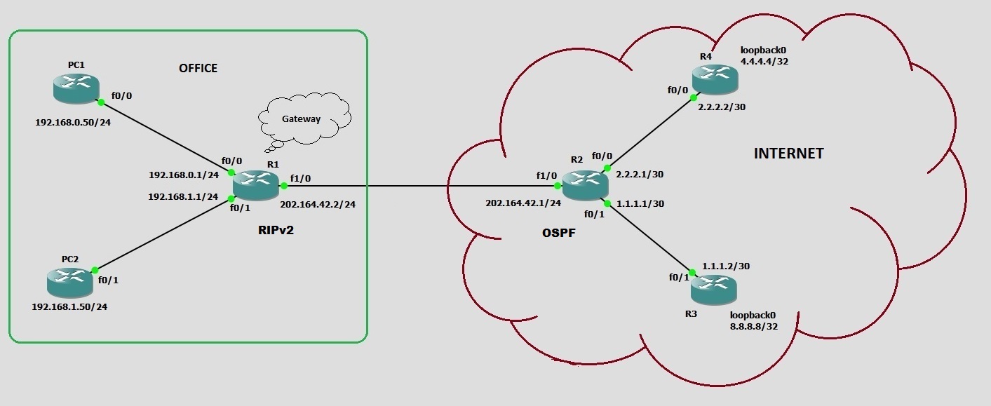
So in order to redistribute RIPv2 routes into other routers, the router R2 which is directly connected to R1, R2 need to run both RIPv2 as well as OSPF.
Remove other routing protocols from R1 and configure RIPv2
R1#config t
R1(config)#do sho ip protocols
Routing Protocol is "ospf 20"
  Outgoing update filter list for all interfaces is not set
  Incoming update filter list for all interfaces is not set
  Router ID 4.4.4.4
  Number of areas in this router is 1. 1 normal 0 stub 0 nssa
  Maximum path: 4
  Routing for Networks:
    192.168.0.0 0.0.0.255 area 0
    192.168.1.0 0.0.0.255 area 0
    202.164.42.0 0.0.0.255 area 0
 Reference bandwidth unit is 100 mbps
  Routing Information Sources:
    Gateway         Distance      Last Update
    8.8.8.8              110      00:01:57
    202.164.42.1         110      00:01:57
  Distance: (default is 110)

R1(config)#no router ospf 20
R1(config)#no ip route 0.0.0.0 0.0.0.0
*Jul  1 09:52:55.931: %OSPF-5-ADJCHG: Process 20, Nbr 202.164.42.1 on FastEthernet1/0 from FULL to DOWN, Neighbor Down: Interface down or detached
R1(config)#router rip
R1(config-router)#network 192.168.0.0
R1(config-router)#network 192.168.1.0
R1(config-router)#network 202.164.42.0
R1(config-router)#version 2
R1(config-router)#no auto-summary
R1(config-router)#^Z
R1#
Line marked red will disable ospf process on router and the line marked green will remove the default route. Then I enabled RIPv2.
Now let’s move ahead to R2 and configure RIPv2 side by side with OSPF.
R2(config)#router rip
R2(config-router)#network 202.164.42.0
R2(config-router)#network 1.1.1.0
R2(config-router)#network 2.2.2.0
R2(config-router)#version 2
R2(config-router)#no auto-summary
R2(config-router)#^Z
R2#
After enabling RIP on Router R2, verify the routing protocols using show ip protocols command
R2#show ip protocols
Routing Protocol is "ospf 123"
  Outgoing update filter list for all interfaces is not set
  Incoming update filter list for all interfaces is not set
  Router ID 202.164.42.1
  Number of areas in this router is 1. 1 normal 0 stub 0 nssa
  Maximum path: 4
  Routing for Networks:
    1.1.1.1 0.0.0.0 area 0
    2.2.2.0 0.0.0.255 area 0
    202.164.42.0 0.0.0.255 area 0
 Reference bandwidth unit is 100 mbps
  Routing Information Sources:
    Gateway         Distance      Last Update
    8.8.8.8              110      00:28:05
    4.4.4.4              110      00:28:05
  Distance: (default is 110)

Routing Protocol is "rip"
  Outgoing update filter list for all interfaces is not set
  Incoming update filter list for all interfaces is not set
  Sending updates every 30 seconds, next due in 25 seconds
  Invalid after 180 seconds, hold down 180, flushed after 240
  Redistributing: rip
  Default version control: send version 2, receive version 2
    Interface             Send  Recv  Triggered RIP  Key-chain
    FastEthernet0/0       2     2
    FastEthernet0/1       2     2
    FastEthernet1/0       2     2
  Automatic network summarization is not in effect
    Interface             Send  Recv  Triggered RIP  Key-chain
  Maximum path: 4
  Routing for Networks:
    1.0.0.0
    2.0.0.0
    202.164.42.0
  Routing Information Sources:
    Gateway         Distance      Last Update
    202.164.42.2         120      00:00:30
  Distance: (default is 120)

R2#show ip route
Codes: C - connected, S - static, R - RIP, M - mobile, B - BGP
[output cut]

Gateway of last resort is not set

     1.0.0.0/30 is subnetted, 1 subnets
C       1.1.1.0 is directly connected, FastEthernet0/1
     2.0.0.0/30 is subnetted, 1 subnets
C       2.2.2.0 is directly connected, FastEthernet0/0
     4.0.0.0/32 is subnetted, 2 subnets
O       4.4.4.4 [110/2] via 2.2.2.2, 00:29:42, FastEthernet0/0
S       4.4.4.0 [150/0] via 2.2.2.2
     8.0.0.0/32 is subnetted, 1 subnets
O       8.8.8.8 [110/2] via 1.1.1.2, 00:29:42, FastEthernet0/1
R    192.168.0.0/24 [120/1] via 202.164.42.2, 00:00:01, FastEthernet1/0
R    192.168.1.0/24 [120/1] via 202.164.42.2, 00:00:01, FastEthernet1/0
C    202.164.42.0/24 is directly connected, FastEthernet1/0
R2#
The routing table of R2 is showing routes from RIP as well as routes from OSPF. This is pretty natural because the router is running both protocols.
Now, come to main step which is to setup redistribution
R2#conf t
Enter configuration commands, one per line.  End with CNTL/Z.
R2(config)#router ospf 123
R2(config-router)#redistribute rip metric 5000 subnets
R2(config-router)#redistribute connected subnets
R2(config-router)#exit
R2(config)#router rip
R2(config-router)#redistribute ospf 123 metric 3
R2(config-router)#passive-interface fastEthernet 0/0
R2(config-router)#passive-interface fastEthernet 0/1
R2(config-router)#end
R2#
Firstly, I entered OSPF routing protocol config mode and typed redistribute rip metric 5000 subnets command. This is telling OSPF to advertise RIP routes including subnets with the metric of 5000 [Remember OSPF uses cost value as metric]. The redistribute connected subnets command will allow R2 to incluse directly connected subnets into OSPF LSAs.
Secondly, I entered RIP routing protocl config mode and typed redistribute ospf 123 metric 3 command. This command is telling RIP to advertise OSPF routes with the metric of 3. [Remember RIP uses hop count as metric]. The passive-interface command is used to disable RIP updates from being sent through FastEthernet0/0 and FastEthernet0/1 because R2 only need to send RIP updates through FastEthernet1/0 which is directly connected to our router R1.
After redistribution is configured, let’s verify the routing table of all routers.
On R1:
R1#show ip route
[output cut]

Gateway of last resort is not set

     1.0.0.0/30 is subnetted, 1 subnets
R       1.1.1.0 [120/1] via 202.164.42.1, 00:00:17, FastEthernet1/0
     2.0.0.0/30 is subnetted, 1 subnets
R       2.2.2.0 [120/1] via 202.164.42.1, 00:00:17, FastEthernet1/0
     4.0.0.0/32 is subnetted, 1 subnets
R       4.4.4.4 [120/3] via 202.164.42.1, 00:00:17, FastEthernet1/0
     8.0.0.0/32 is subnetted, 1 subnets
R       8.8.8.8 [120/3] via 202.164.42.1, 00:00:17, FastEthernet1/0
C    192.168.0.0/24 is directly connected, FastEthernet0/0
C    192.168.1.0/24 is directly connected, FastEthernet0/1
C    202.164.42.0/24 is directly connected, FastEthernet1/0
R1#
In R1’s routing table, you can see that all the routes to remote networks are leared via RIP as denoted by R.
On R2:
R2#show ip route
[output cut]

Gateway of last resort is not set

     1.0.0.0/30 is subnetted, 1 subnets
C       1.1.1.0 is directly connected, FastEthernet0/1
     2.0.0.0/30 is subnetted, 1 subnets
C       2.2.2.0 is directly connected, FastEthernet0/0
     4.0.0.0/32 is subnetted, 1 subnets
O       4.4.4.4 [110/2] via 2.2.2.2, 01:02:56, FastEthernet0/0
     8.0.0.0/32 is subnetted, 1 subnets
O       8.8.8.8 [110/2] via 1.1.1.2, 01:02:56, FastEthernet0/1
R    192.168.0.0/24 [120/1] via 202.164.42.2, 00:00:03, FastEthernet1/0
R    192.168.1.0/24 [120/1] via 202.164.42.2, 00:00:03, FastEthernet1/0
C    202.164.42.0/24 is directly connected, FastEthernet1/0
R2#
In R2’s routing table, you can see the routes from both RIP as well as OSPF sice the R2 is running both routing protocols.
On R3:
R3#show ip route
[output cut]

Gateway of last resort is not set

     1.0.0.0/30 is subnetted, 1 subnets
C       1.1.1.0 is directly connected, FastEthernet0/1
     2.0.0.0/30 is subnetted, 1 subnets
O       2.2.2.0 [110/2] via 1.1.1.1, 01:06:59, FastEthernet0/1
     4.0.0.0/32 is subnetted, 1 subnets
O       4.4.4.4 [110/3] via 1.1.1.1, 01:06:59, FastEthernet0/1
     8.0.0.0/32 is subnetted, 1 subnets
C       8.8.8.8 is directly connected, Loopback0
O E2 192.168.0.0/24 [110/5000] via 1.1.1.1, 01:06:59, FastEthernet0/1
O E2 192.168.1.0/24 [110/5000] via 1.1.1.1, 01:06:59, FastEthernet0/1
O    202.164.42.0/24 [110/2] via 1.1.1.1, 01:06:59, FastEthernet0/1
R3#
In R3’s routing table, you can see the RIP routes advertised through OSPF. These routes are denoted by O E2.
On R4:
R4#show ip route
[output cut]

Gateway of last resort is not set

     1.0.0.0/30 is subnetted, 1 subnets
O       1.1.1.0 [110/2] via 2.2.2.1, 01:09:52, FastEthernet0/0
     2.0.0.0/30 is subnetted, 1 subnets
C       2.2.2.0 is directly connected, FastEthernet0/0
     4.0.0.0/32 is subnetted, 1 subnets
C       4.4.4.4 is directly connected, Loopback0
     8.0.0.0/32 is subnetted, 1 subnets
O       8.8.8.8 [110/3] via 2.2.2.1, 01:09:52, FastEthernet0/0
O E2 192.168.0.0/24 [110/5000] via 2.2.2.1, 01:09:52, FastEthernet0/0
O E2 192.168.1.0/24 [110/5000] via 2.2.2.1, 01:09:52, FastEthernet0/0
O    202.164.42.0/24 [110/2] via 2.2.2.1, 01:09:52, FastEthernet0/0
R4#
In R4’s routing table, you can see the RIP routes advertised through OSPF denoted by O E2 similar to R3.
Verify the network connectivity
Now it is time to verify if our network is working after route redistribution. You can verify this by running ping from PC1 or PC2 to end router (8.8.8.8).
PC1#ping 8.8.8.8

Type escape sequence to abort.
Sending 5, 100-byte ICMP Echos to 8.8.8.8, timeout is 2 seconds:
!!!!!
Success rate is 100 percent (5/5), round-trip min/avg/max = 64/292/1136 ms
PC1#
This conclude our route distribution is successfully configured and working properly.
Now you have learned about all the routing protocols, I am giving a quick recap of all routing protocols.
Quick Recap of Routing Protocols
- RIPv1: RIPv1 is legacy clasful routing protocol which sends full routing table by using broadcasts every 30 seconds and has an AD of 120. It does not support authentication.
- RIPv2: RIPv2 is classless routing protocols which sends multicasts (224.0.0.9) every 30 seconds and also has an AD of 120. RIPv2 sends subnet mask information with the route updates, which allows it to support classless networking and discontiguous networks. It supports authentication between routers.
- EIGRP: EIGRP is a classless, advanced distance-vector protocol that supports IP, IPX, AppleTalk, and now IPv6. EIGRP uses a unique algorithm, called DUAL, to maintain route information and uses RTP to communicate with other EIGRP routers reliably. It has default AD of 90.
- OSPF: OSPF is a link-state Open standard protocol that supports VLSM and classless routing. It has default AD of 110.
- Redistribution: Redistribution is the process of a routing protocol to advertise routes that are learned by another routing protocol, static routes, or directly connected routes.