
- July 4, 2015
- Posted by: Surender Kumar
- Category: Cisco Switches
Layer 2 Switching
Table of Contents
Before the concept of Switching, Ethernet Hubs or multi-port repeaters were used to connect multiple computers or other network devices together. Hubs are now replaced by network switches due to various advancements and features.
Difference Between Hubs and Switches
| Hubs | Switches | |
| Function | Connects many network device together so that devices can exchange data. Do not provide any security feature | Switch is used to connect many devices together on a computer network. It offers VLAN and other security features |
| OSI Model Layer | Hub works on physical layer (layer-1) of OSI Model | Switch works on Data-Link Layer (layer-2) of OSI Model. Layer 3 switches work on Network layer |
| Data Transmission Unit | Electrical signal or bits | Frames for L2 Switch and Packets for L3 switch |
| Transmission Type | Hubs always perform frame broadcast | First broadcast; then unicast and multicast |
| Ports | Hubs have up to24 ports | Switch has generally more ports (upto 48 ports) |
| Address Learning | A network hub cannot learn and store MAC addresses | A network switch stores MAC addresses in a MAC address table |
| Transmission Mode | Half duplex | Full duplex |
| Broadcast Domain | Hubs have one Broadcast Domain. All the connected devices remain in same broadcast domain | Switch by default has one broadcast domain but can create multiple broadcast domains with VLANs |
| Collisions | Collisions are common in networks | No collisions occur in a full-duplex switch environment |
| Loop Avoidance | No means of loop avoidance | Spanning Tree Protocol is used to avoid switching loops |
Difference between Bridges and Switches
| Bridge | Switch |
| A device used to connect two separate Ethernet networks into one extended Ethernet. Bridge has usually 2 ports to connect two segments | Switch is a multi-port bridge. It can have up to 48 ports and each port works as bridge port |
| Bridge uses software to create and manage filter tables | Switches use Application Specific Integrated Circuits (ASIC) to build and maintain filter table |
| A bridge can support only one spanning tree instance | Switch supports multiple spanning tree instances at the same time |
How Layer 2 Switching Works
Layer 2 switching uses the Media Access Control (MAC) address from the host’s network interface cards to decide where to forward frames. Layer 2 switching is hardware-based, which means switches use application specific integrated circuit (ASIC) to build and maintain MAC address tables or CAM tables.
Functions of Switch at Layer 2
The switch performs three distinct functions at layer 2 which are:
- MAC Address Learning
- Forwarding/filtering Decision
- Loop Avoidance
Let’s discuss about these functions of switch in detail.
- MAC Address Learning: When a switch is switched on, it does not know the address of any host connected to network. When a device transmits for the first time, the switch stores the source MAC address and the interface ID from which the frame is received into a table which is known as MAC address table, CAM table or Filter table. Since the switch do not have information about any other host on network, it will broadcast the frame to all ports except that of source port. When the destination hosts reply to the broadcasted frame, switch will store store its MAC address by looking into frame and interface ID the host is connected to. The process is repeated until switch learn MAC address of all the connected hosts.
- Forwarding/filtering Decision: When a frame is received on any interface, the switch will look into the destination address and compare to its MAC address table. If the destination address is found in table, switch will not broadcast the frame but it will unicast the frame to interface corresponding to destination MAC address. But if the address is not found in filter table, the switch will flood the frame to find out destination. This is called filtering since the switch is filtering unnecessary traffic on network. The switch makes the forward or filter decision on the basis of MAC address table.
- Loop Avoidance: In production networks, the switches are interconnected to each other using multiple or redundant links. Redundancy is good for the times when one of the link fails, the redundant link can keep the network working. But this redundancy can also cause a big problem which is known as switching loop or broadcast storm.
Understanding Switching Loop or Broadcast Storm
Consider the following network diagram to better understand how switching loop works
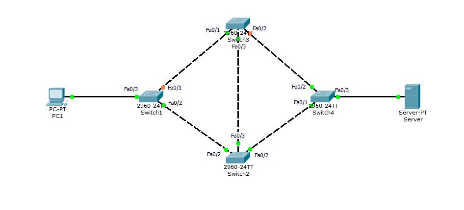 When PC1 try to connect to Server for the first time, Switch1 will receive the frame at interface Fa0/3 and since the Server is connected to Switch4, it is obvious that it will not find Server’s MAC address in its filter table. Switch1 will then flood the frame out of every port except Fa0/3. Now, both Switch2 and Switch3 will receive the copy of same frame. Switch2 and Switch3 will also flood the frame out every port (except source port). With this broadcast (flood), Switch1 can receive the frame back either via Switch2 — Switch3 — Switch1 or via Switch3 — Switch2 — Switch1. The Switch1 received its original frame back, So it will use the same method to flood it again in the search of Server. In this way the frame will keep circulating in network and copies of frame will keep increasing with each loop. As an end result, the whole network bandwidth will be eaten by this unnecessary broadcast storm, resulting in complete network breakdown or unexpected result like super slow network performance.
Spanning Tree Protocol was designed to avoid layer 2 switching loop and broadcast storms. Spanning Tree Protocol is discussed in next section.